Method for calibrating a vehicle control unit via a voltage supply line, and a correspondingly calibratable vehicle control unit

a vehicle control unit and voltage supply line technology, applied in the direction of memory architecture accessing/allocation, instruments, transportation and packaging, etc., can solve the problems of not being suited for standard applications, requiring a large amount of time and effort, and being prone to complex and/or slow, etc., to reduce the manufacturing effort and the manufacturing cost of the control unit, and reduce the effort in construction.

Active Publication Date: 2019-12-26
ROBERT BOSCH GMBH
View PDF1 Cites 0 Cited by
  • Summary
  • Abstract
  • Description
  • Claims
  • Application Information

AI Technical Summary

Benefits of technology

[0011]The present invention in this case offers the advantage that both a supply voltage may be applied and a communication signal may be received via the voltage supply line. This is advantageous, in particular, because it is not necessary to design two separate interfaces for receiving the communication signal and the supply voltage, but that for this purpose a connection preferably already designed in or on the control unit for connection with the voltage supply line may also be used for receiving the communication signal. This may reduce the manufacturing effort and the manufacturing costs of the control unit. The control unit may be manufactured, in particular, as a compact unit since, according to the present invention, the control unit does not necessarily have to include for calibration a reserved interface for receiving the communication signal. In this case, the present invention preferably employs established methods of carrier-frequency technology as used, in particular, in carrier-frequency systems (TFA), for example, the so-called powerline technology (also known as PowerLAN or Powerline Communication (PLC)) for home applications. Although not suited for standard applications in the vehicle for lack of corresponding transmission reliability and due to special requirements in the automotive sector such as, for example, environmental requirements (temperature, vibration, EMV . . . ) as well as size in the control unit and costs for the large-scale production, it was nevertheless found in conjunction with the present invention that a calibration process may be advantageously carried out using these technologies, since this calibration process does not impose such requirements.
[0012]The present invention also offers the advantage that no mechanical retrofitting of the control unit is required for removing a reserved interface for receiving the communication signal, such as, for example, manufacturing a housing opening for a cable feed-through or reserving control unit plug pins, thereby significantly reducing the expenditure of effort in constructing the control unit for calibration.
[0013]The present invention also offers the advantage that the access to the control unit need not be limited to one particular location within the vehicle, such as, for example, to the engine compartment, but is, in principle, possible wherever the on-board voltage of the vehicle is present or may be tapped or is accessible. This may be the case, for example, in a luggage compartment and / or in a passenger compartment of the vehicle. Thus, the control unit may preferably be placed at virtually any position in the vehicle, since only one access to the automotive electrical system voltage is sufficient for the data exchange. Accordingly, a connection suitable for transmitting or feeding or modulating the communication signal may be designed at virtually any location in the motor vehicle. A measuring and calibration system may, for example, be equipped with a corresponding coupling module, which enables a transmission and / or feeding and / or modulation of the communication signal to the supply voltage or automotive electrical system voltage.

Problems solved by technology

However, this frequently requires a mechanical retrofitting of the control unit, which may be associated with a significant expenditure of time and effort.
Such interfaces may be optimized for their regular use, which is why these interfaces are potentially only partially suitable for use in calibrating the control unit and a calibration of the control unit with the aid of such interfaces available in series is potentially very complex and / or slow and / or may be used only for a limited range of functions.
Although not suited for standard applications in the vehicle for lack of corresponding transmission reliability and due to special requirements in the automotive sector such as, for example, environmental requirements (temperature, vibration, EMV .

Method used


Image

  • Method for calibrating a vehicle control unit via a voltage supply line, and a correspondingly calibratable vehicle control unit

Examples


Embodiment Construction

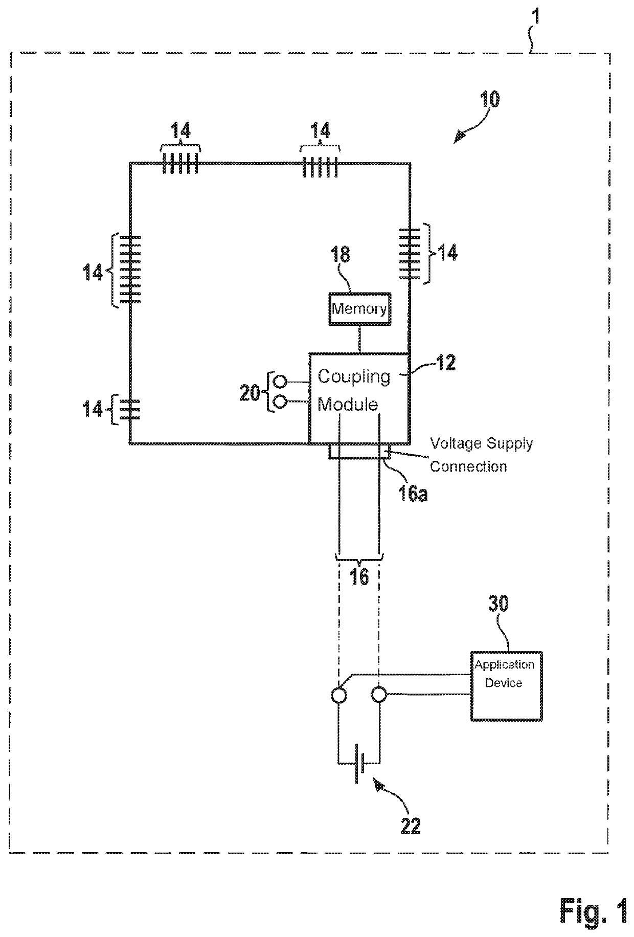
[0021]FIG. 1 shows a schematic representation of a vehicle control unit 10 according to one preferred specific embodiment in a vehicle 1, for example, a motor vehicle. Vehicle control unit 10 (hereinafter: control unit) may be designed, for example, as an engine control unit for controlling an internal combustion engine, a clutch control unit for controlling a clutch, a battery control unit for controlling a vehicle battery, an E-control unit for controlling an electric machine, etc.

[0022]The control unit in the specific embodiment shown includes a coupling module 12, which is integrated into control unit 10 and, in this way, forms a structural unit with control unit 10. According to another specific embodiment, the coupling module may also be situated outside control unit 10, which may be advantageous, for example, for small control units with small available space. In addition, control unit 10 also includes multiple serial interfaces 14, which are used to receive and / or to transmi...


PUM


Abstract

A method is described for calibrating a vehicle control unit, a data exchange taking place via a voltage supply line connected to the vehicle control unit, as well as a vehicle control unit, which is configured to carry out a data exchange for calibrating the vehicle control unit via a voltage supply line connected to the vehicle control unit with the aid of a communication signal (powerline communication) modulated to the supply voltage. A corresponding measuring and calibration system is also described.

Description

FIELD OF THE INVENTION[0001]The present invention relates to a method for calibrating a vehicle control unit, a vehicle control unit and a vehicle that includes such a vehicle control unit, as well as a measuring and calibration system.BACKGROUND INFORMATION[0002]Modern technical processes, to the extent they are controlled by processing units, so-called control units, may be calibrated to achieve series production readiness (so-called application). In the process, various parameters of the control unit software are adapted to the specific operational purpose, for example, in the vehicle, via extensive measurements and adjustments. Parameters of functional algorithms in particular, (control functions, regulating functions, diagnostic functions) are adapted to different vehicle models or vehicle variants without the need to change calculation routines. At the same time, signals from control units, vehicle busses and measuring devices are detected so that the effects of the adjustment...

Claims


Application Information

Patent Timeline
Patent Type & Authority Applications(United States)
IPC IPC(8): B60R16/033H02J7/02
CPCB60W2050/0063H02J7/025G06F2212/173B60R16/033B60R16/03B60R16/023H02J50/10
Inventor ABERFELD, ANDREASLOEWL, WOLFGANG
Owner ROBERT BOSCH GMBH
Why Eureka
Try Eureka