
Steerable drill for minimally-invasive surgery

a minimally invasive surgery and drill bit technology, applied in boring/drilling machines, manufacturing tools, surgery, etc., can solve the problems of incomplete removal of necrotic bone, limited access and debridement of the entire lesion, and collapse of the subchondral bone, so as to achieve controllable bending angle and facilitate bending

Pending Publication Date: 2020-01-02
THE JOHN HOPKINS UNIV SCHOOL OF MEDICINE
View PDF6 Cites 20 Cited by
  • Summary
  • Abstract
  • Description
  • Claims
  • Application Information

AI Technical Summary

Benefits of technology

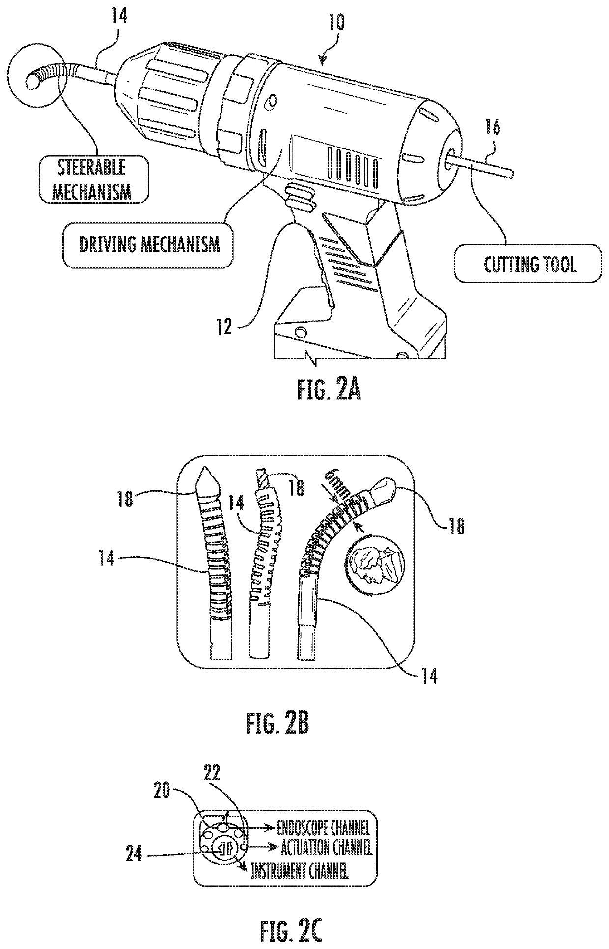
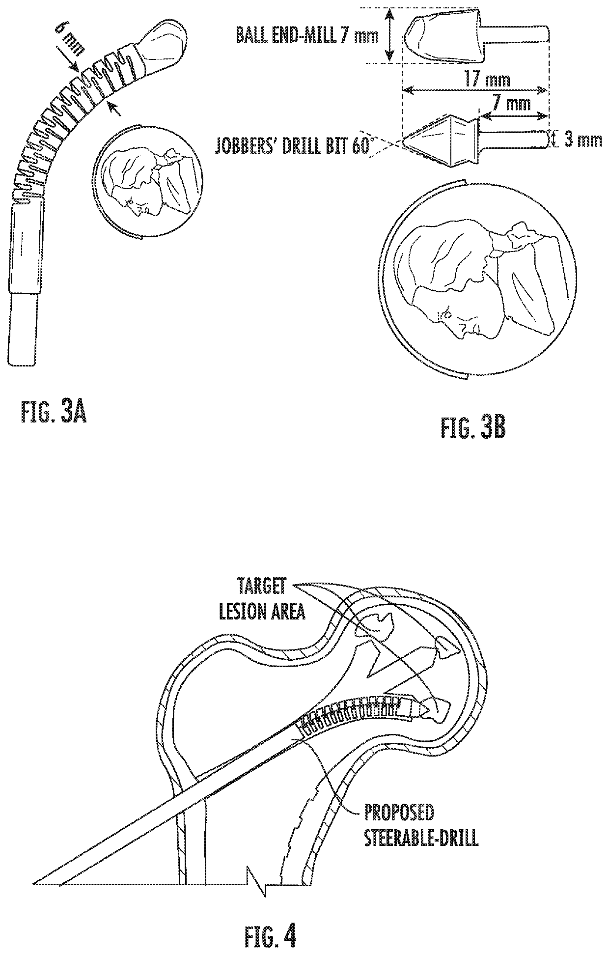
The present invention is a drilling device with a steerable mechanism that allows for controlled bending. It includes a flexible cable that actuates the bending angle, and a cutting tool that can be placed through the inner lumen of the steerable mechanism. The drilling device also has a driving mechanism for controlling the bending angle, with a motor and battery. The steerable mechanism can be controlled through a joystick or directional control buttons, or through robotic control. It is made of a metal such as titanium or nitinol, with notches along its length to facilitate bending. The cutting tool is a ball end-mill and has a flexible distal end. The patent is useful for those who need to drill holes in difficult-to-reach areas, or in areas where there are no pre-existing holes.

Problems solved by technology

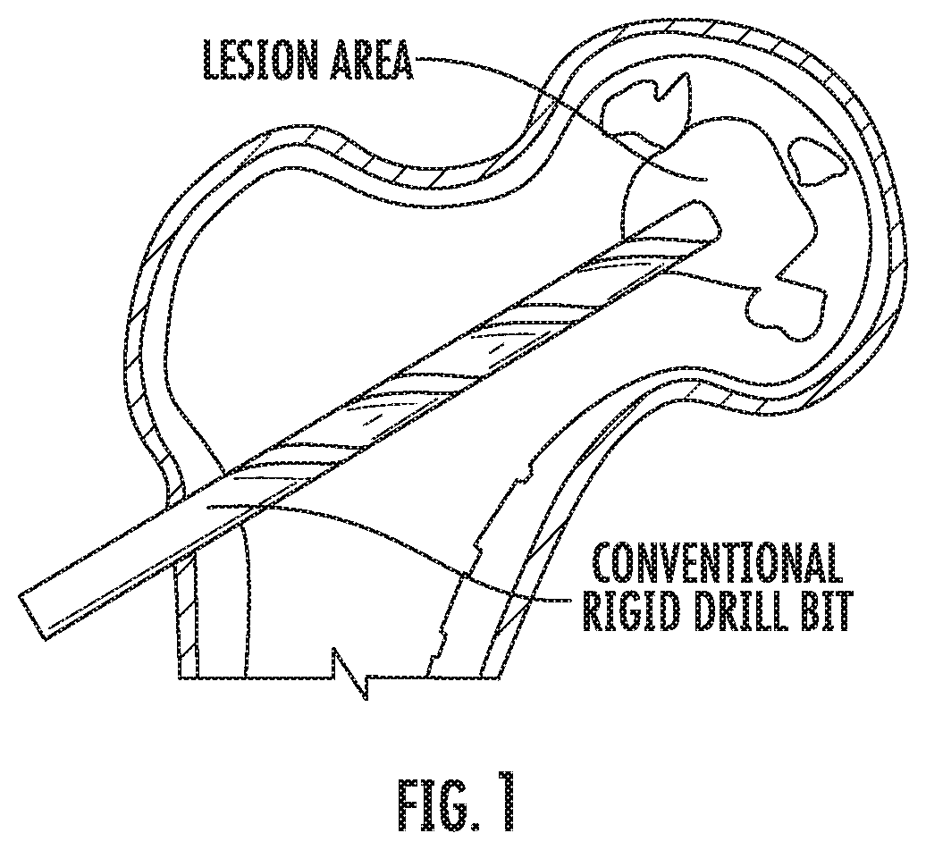
Osteonecrosis disrupts blood supply to the femoral head which causes pain and eventually leads to collapse of the subchondral bone.
However, due to individual variation in distributions, sizes and shapes of the necrotic lesion, utilizing conventional rigid tools limit accessibility and debridement of the entire lesion.
This results in incomplete removal of the necrotic bone and potential collapse or damage to the cartilage overlying the femoral head.

Method used


Image

  • Steerable drill for minimally-invasive surgery
  • Steerable drill for minimally-invasive surgery
  • Steerable drill for minimally-invasive surgery

Examples


Embodiment Construction

[0030]The presently disclosed subject matter now will be described more fully hereinafter with reference to the accompanying Drawings, in which some, but not all embodiments of the inventions are shown. Like numbers refer to like elements throughout. The presently disclosed subject matter may be embodied in many different forms and should not be construed as limited to the embodiments set forth herein; rather, these embodiments are provided so that this disclosure will satisfy applicable legal requirements. Indeed, many modifications and other embodiments of the presently disclosed subject matter set forth herein will come to mind to one skilled in the art to which the presently disclosed subject matter pertains having the benefit of the teachings presented in the foregoing descriptions and the associated Drawings. Therefore, it is to be understood that the presently disclosed subject matter is not to be limited to the specific embodiments disclosed and that modifications and other ...


PUM

PropertyMeasurementUnit
diameteraaaaaaaaaa
diameteraaaaaaaaaa
feed-velocityaaaaaaaaaa

Abstract

An embodiment in accordance with the present invention provides a continuum dexterous manipulator (CDM) with a specially designed flexible tool, to be used as a handheld or robotic steerable device for treatment of hard-tissue-related diseases. The CDM of the present invention works well in treatment of soft and sticky material (similar to a lesion) as well as milling the hard tissues (e.g. sclerotic liner of osteolytic lesions) and bone tumors. The present invention is also directed to flexible drilling tools as well as characterization and evaluation of integrating these tools with the CDM in curved-drilling of hard bone towards treatment of hard tissue related diseases (e.g. osteonecrosis or pelvic fracture). The present invention can also include use of various types of drill geometries, aspiration and irrigation, and endoscope view in curved-drilling and trajectory planning.

Description

CROSS REFERENCE TO RELATED APPLICATIONS[0001]This application claims the benefit of U.S. Provisional Patent Application No. 62 / 466,424, filed Mar. 3, 2017, which is incorporated by reference herein, in its entirety.GOVERNMENT SUPPORT[0002]This invention was made with government support under R01EB016703-01A1 awarded by the National Institutes of Health. The government has certain rights in the invention.FIELD OF THE INVENTION[0003]The present invention relates generally to medical devices. More particularly, the present invention relates to a steerable device for treatment of hard-tissue-related diseases and for minimally-invasive surgery.BACKGROUND OF THE INVENTION[0004]More than 20,000 patients are diagnosed each year with osteonecrosis of the femoral head, most of them aged between 20 and 50 years. Delayed treatment of these patients leads to total hip arthroplasty (THA) surgery. Osteonecrosis disrupts blood supply to the femoral head which causes pain and eventually leads to col...

Claims


Application Information

Patent Timeline
Patent Type & Authority Applications(United States)
IPC IPC(8): A61B17/16A61B17/00
CPCA61B2017/003A61B17/1631A61B17/1617A61B17/1642A61B17/00234A61B17/1626B23B39/14A61B2017/00309A61B2017/00323A61B17/1622
Inventor ALAMBEIGI, FARSHIDARMAND, MEHRAN
Owner THE JOHN HOPKINS UNIV SCHOOL OF MEDICINE
Learn More