
Hydrogen gas compressing system and hydrogen gas compression method

Inactive Publication Date: 2020-01-02
TOYOTA JIDOSHA KK
View PDF13 Cites 1 Cited by
  • Summary
  • Abstract
  • Description
  • Claims
  • Application Information

AI Technical Summary

Benefits of technology

The patent describes a system, method, or technique for storing, compressing, or using hydrogen gas. The technical effects of this patent may involve improved efficiency, reliability, or safety in the use of hydrogen gas in various applications such as fuel cells or industrial processes.

Problems solved by technology

This configuration requires a compressor and has a problem of a large compression cost for the hydrogen gas supply.
This has another problem of a large storage cost.

Method used


Image

  • Hydrogen gas compressing system and hydrogen gas compression method
  • Hydrogen gas compressing system and hydrogen gas compression method
  • Hydrogen gas compressing system and hydrogen gas compression method

Examples


first embodiment

A. First Embodiment

A1. System Configuration

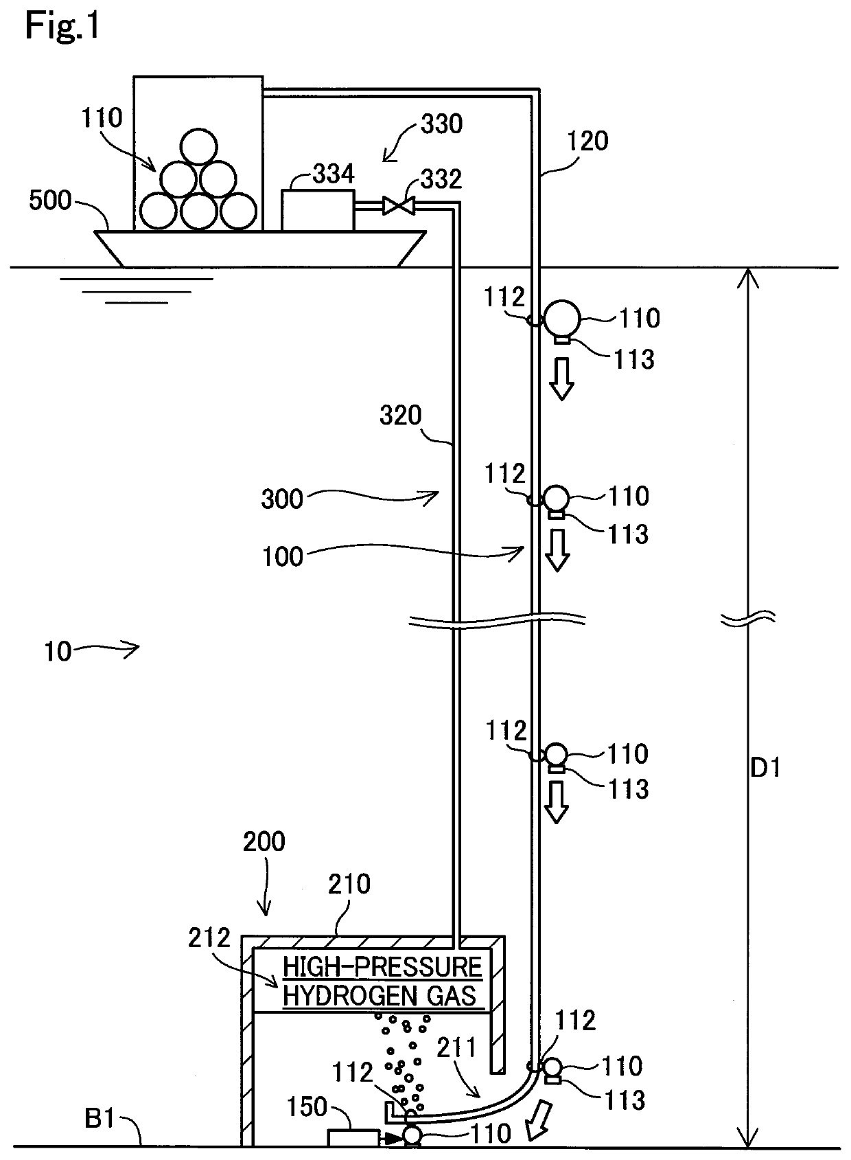
[0010]FIG. 1 is a diagram illustrating the schematic configuration of a hydrogen gas compression system 10 according to one embodiment of the present disclosure. The hydrogen gas compression system 10 uses the hydraulic pressure in the sea to compress hydrogen gas and stores the compressed hydrogen gas. The hydrogen gas compression system 10 includes a transporting portion 100, a gas release portion 150, a storage portion 200 and a recovery portion 300.

[0011]The transporting portion 100 is configured to guide a hydrogen container 110 that is filled with hydrogen gas, to a hydrogen storage chamber 210 that is provided in the storage portion 200.

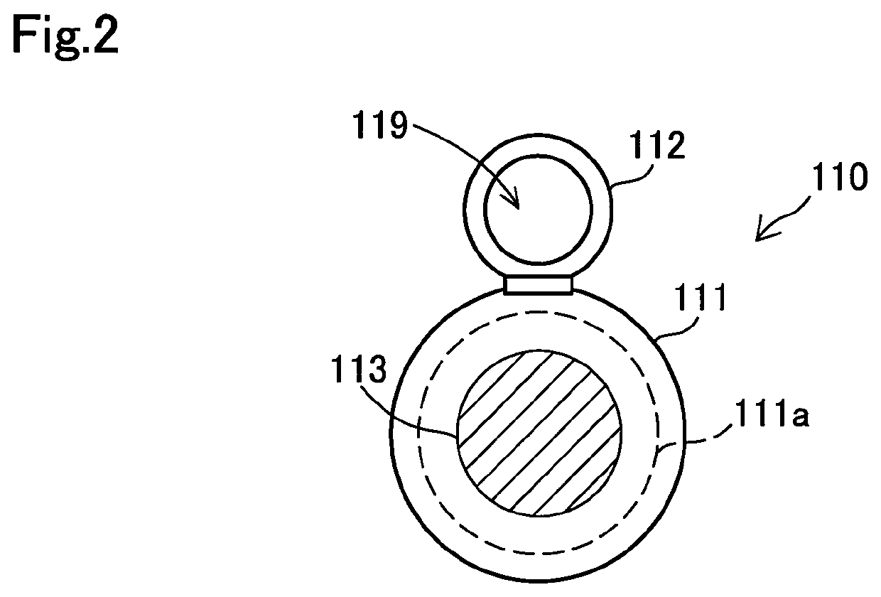
[0012]FIG. 2 is an appearance diagram illustrating the configuration of the hydrogen container 110. The hydrogen container 110 includes a main body portion 111, a mounting portion 112 and a weight portion 113. The main body portion 111 has an approximately spherical appearance shape and has a hydrogen...

second embodiment

B. Second Embodiment

[0024]FIG. 4 is a diagram illustrating the schematic configuration of a hydrogen gas compression system 10a according to a second embodiment. The hydrogen gas compression system 10a of the second embodiment differs from the hydrogen gas compression system 10 of the first embodiment shown in FIG. 1 by that a transporting recovery portion 400 is provided instead of the transporting portion 100 and the recovery portion 300. Otherwise the configuration of the hydrogen gas compression system 10a of the second embodiment is similar to the configuration of the hydrogen gas compression system 10 of the first embodiment. Like components are expressed by like reference signs, and their detailed description is omitted.

[0025]The transporting recovery portion 400 is a functional portion having the combined functions of the transporting portion 100 and the recovery portion 300 of the first embodiment. More specifically, the transporting recovery portion 400 is configured to gu...


PUM

PropertyMeasurementUnit
Pressureaaaaaaaaaa

Abstract

A hydrogen gas compression system comprises a hydrogen storage chamber placed at a predetermined water depth in water to communicate with surrounding water; a hydrogen container filled with hydrogen gas by a lower pressure than a hydraulic pressure at the predetermined water depth; a transporting portion configured to guide the hydrogen container that is filled with the hydrogen gas, from above the predetermined water depth to the hydrogen storage chamber; a gas release portion configured to cause the hydrogen gas to be released from the hydrogen container transported to the hydrogen storage chamber and to be stored in the hydrogen storage chamber; a hydrogen recovery device placed above the predetermined depth; and a tube arranged to connect inside of the hydrogen storage chamber with the hydrogen recovery device.

Description

CROSS REFERENCE TO RELATED APPLICATIONS[0001]The present application claims priority from Japanese patent application 2018-122676 filed on Jun. 28, 2018, the entirety of the content of which is hereby incorporated by reference into this application.BACKGROUNDField[0002]The present disclosure relates to compression and storage of hydrogen gas.Related Art[0003]There has been an increasing demand for hydrogen as a fuel used for power generation of fuel cells or as an industrial material. Hydrogen gas produced in a hydrogen production plant or the like may be compressed in the hydrogen production plant or at a hydrogen gas station before being stored in a container and may be supplied via a dispenser to a fuel consuming device such as a fuel cell vehicle. JP 2017-131862A discloses a configuration of causing hydrogen gas produced by a gas production device to be compressed by a compressor, to be stored temporarily in a pressure accumulator and to be filled into a vehicle via a dispenser....

Claims


Application Information

Patent Timeline
IPC IPC(8): F17C5/06F04B41/02
CPCF17C2225/036F17C2221/012F04B41/02F17C5/06F17C13/002F17C2201/056F17C2223/0123F17C2223/035F17C2227/0157F17C2270/0184F17C1/007F17C2201/0128F17C2201/0133F17C2201/0176F17C2201/052F17C2201/054F17C2203/0617F17C2203/0646F17C2203/0673F17C2203/0685F17C2203/069F17C2205/0188F17C2205/032F17C2223/036F17C2227/0121F17C2270/0128F17C2270/0131Y02E60/32Y02E70/30Y02P90/45
Inventor KONDO, TOSHIYUKISUFU, MASANOSUKEOTOKUBO, KENTAROSASSA, SHINJIANDO, HIROKI
Owner TOYOTA JIDOSHA KK
Learn More