Dynamic amplifier and related gain boosting method

Active Publication Date: 2020-01-02
NOVATEK MICROELECTRONICS CORP
View PDF0 Cites 3 Cited by
  • Summary
  • Abstract
  • Description
  • Claims
  • Application Information

AI Technical Summary

Benefits of technology

The patent is about a new technique for boosting the gain of a dynamic amplifier. The technique aims to increase the amplifier's ability to achieve higher gain and address the issues that were previously present.

Problems solved by technology

However, the variation of common-mode voltage ΔVCM is limited under the power supply voltage VDD of the dynamic amplifier, which further limits the gain A.
However, this implementation requires more capacitors such that the circuit cost may increase, and higher power consumption is required due to the increasing number of capacitors.

Method used


Image

  • Dynamic amplifier and related gain boosting method
  • Dynamic amplifier and related gain boosting method
  • Dynamic amplifier and related gain boosting method

Examples


Embodiment Construction

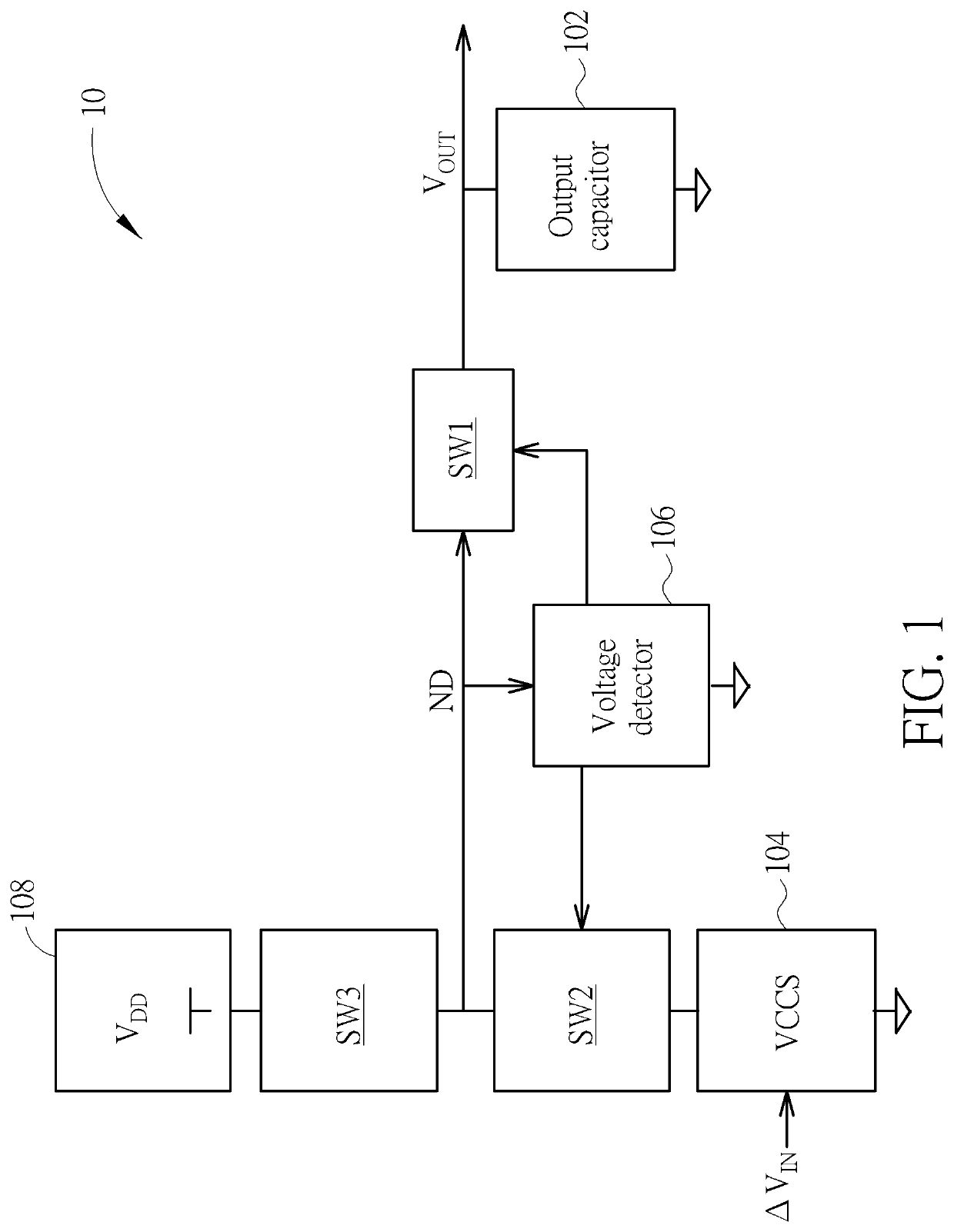
[0027]Please refer to FIG. 1, which is a schematic diagram of a general dynamic amplifier 10. As shown in FIG. 1, the dynamic amplifier 10 includes an output capacitor 102, a voltage-controlled current source (VCCS) 104, a voltage detector 106 and switches SW1-SW3. The dynamic amplifier 10 receives a power supply voltage VDD from a power source 108 which may or may not be included in the dynamic amplifier 10. The VCCS 104 is configured for charging or discharging the output capacitor 102 with a charge or discharge current based on a received input signal ΔVIN, to generate an output signal VOUT by amplifying the input signal ΔVIN. The voltage detector 106, coupled to a voltage detection node ND and the switches SW1 and SW2, is configured for detecting the output voltage of the output capacitor 102 via the voltage detection node ND, and thereby controlling the switches SW1 and / or SW2 to be turned on or off. The switch SW1, coupled between a terminal of the output capacitor 102 and the...


PUM


Abstract

A dynamic amplifier includes a first output capacitor, a first switch, a current source, a second switch, a voltage detector, a third switch and a level shifter. The first switch is coupled between a first terminal of the first output capacitor and a voltage detection node. The second switch is coupled to the current source and the voltage detection node. The voltage detector is coupled to the voltage detection node and the first switch. The third switch is coupled between the voltage detection node and a power source. The level shifter is coupled to a second terminal of the first output capacitor.

Description

BACKGROUND OF THE INVENTION1. Field of the Invention[0001]The present invention relates to a dynamic amplifier, and more particularly, to a gain boosting technique applicable to a dynamic amplifier.2. Description of the Prior Art[0002]A dynamic amplifier has been widely applied in various circuitries, such as an analog to digital converter (ADC), an integrator and an output buffer. Both a dynamic amplifier and a general operational amplifier provide a specific gain for amplifying input signals. The difference between the dynamic amplifier and the general operational amplifier is that, the general operational amplifier performs continuous-time operations while the dynamic amplifier performs discrete-time operations. Thus, the dynamic amplifier is applicable to a discrete-time circuit system such as a residue amplifier of a pipeline ADC and a discrete-time delta-sigma modulator (DSM) ADC.[0003]The dynamic amplifier receives a differential pair of input signals, which generate differen...

Claims


Application Information

Patent Timeline
IPC IPC(8): H03F1/02H03F3/00H03F3/45H03G1/00
CPCH03K19/018585H03F3/45475H03F1/0211H03G1/007H03F3/005H03F3/45179H03F2203/45288H03F3/45479H03F3/45183H03G1/0029H03G1/0094
Inventor HSIEH, CHENG-ENLIU, SHEN-IUANTZENG, TZU-CHIENLIN, JIN-YIHUANG, KUO-SHENGHUANG, JU-LIN
Owner NOVATEK MICROELECTRONICS CORP
Why Eureka
Try Eureka