Electric potentially-driven shade with improved coil strength, and/or method of making the same

Active Publication Date: 2020-01-09
GUARDIAN GLASS LLC
View PDF1 Cites 0 Cited by
  • Summary
  • Abstract
  • Description
  • Claims
  • Application Information

AI Technical Summary

Benefits of technology

[0004]In this regard, because windows are usually the “weak link” in a building's isolation, and considering modern architectural designs that often include whole glass facades, it becomes apparent that having better insulating windows would be advantageous in terms of controlling and reducing energy waste. There are, therefore, significant advantages both environmentally and economically in developing highly insulating windows.
[0005]Insulating glass units (IG units or IGUs) have been developed and provide improved insulation to buildings and other structures, and FIG. 1 is a cross-sectional, schematic view of an example IG unit. In the FIG. 1 example IG unit, first and second substrates 102 and 104 are substantially parallel and spaced apart from one another. A spacer system 106 is provided at the periphery of the first and second substrates 102 and 104, helping to maintain them in substantially parallel spaced apart relation to one another and helping to define a gap or space 108 therebetween. The gap 108 may be at least partially filled with an inert gas (such as, for example, Ar, Kr, Xe, and/or the like) in some instances, e.g., to improve the insulating properties of the overall IG unit. Optional outer seals may be provided in addition to the spacer system 106 in some instances.
[0006]Windows are unique elements in most buildings in that they have the ability to “supply” energy to the building in the form of winter solar gain and daylight year

Problems solved by technology

Operational costs, such as heating, cooling, ventilation, and lighting account for the better part of this consumption, especially in older structures built under less stringent energy efficiency construction standards.
However, they oftentimes also represent a significant sourc

Method used


Image

  • Electric potentially-driven shade with improved coil strength, and/or method of making the same
  • Electric potentially-driven shade with improved coil strength, and/or method of making the same
  • Electric potentially-driven shade with improved coil strength, and/or method of making the same

Examples


Embodiment Construction

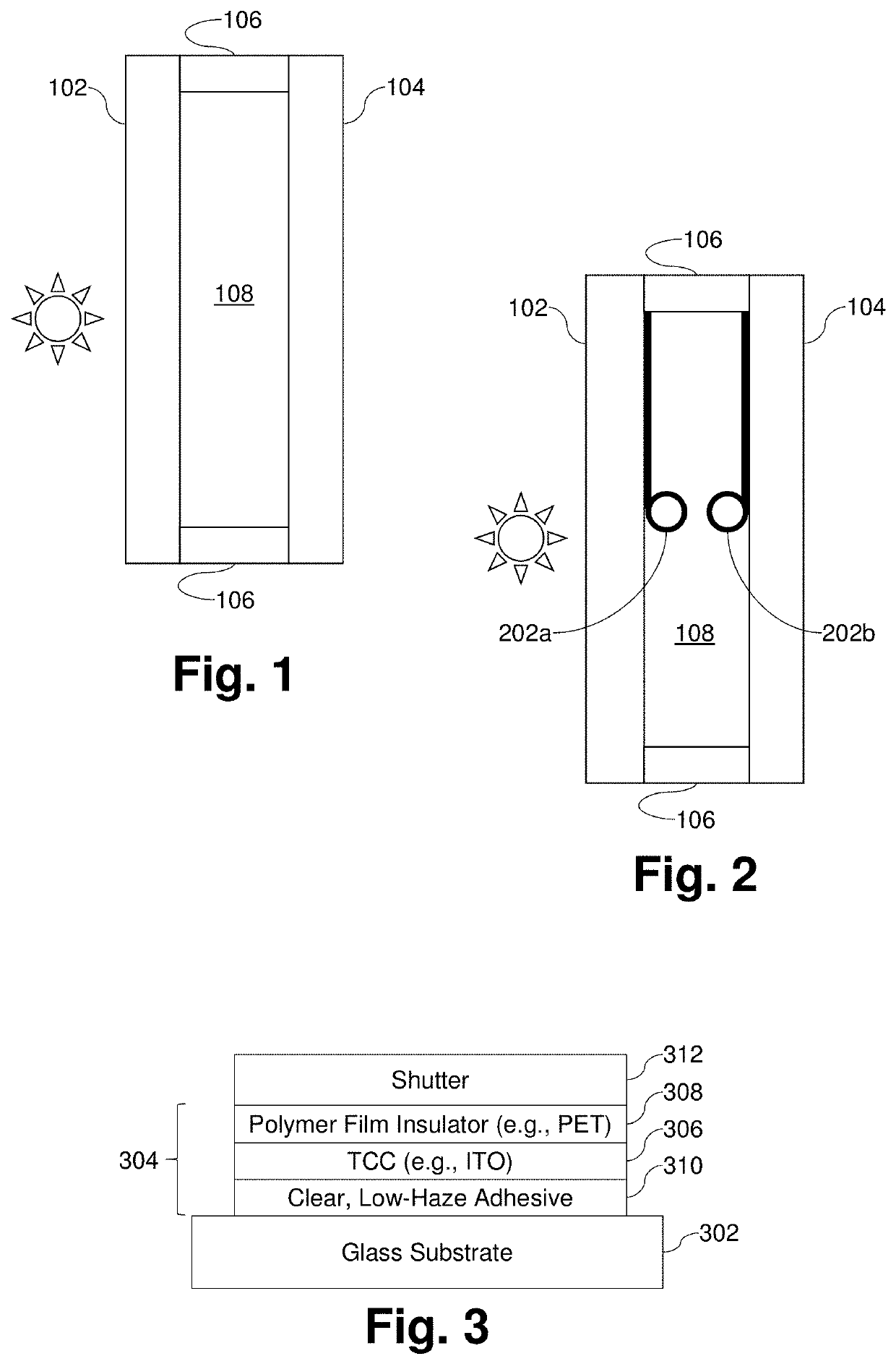
[0033]Certain example embodiments of this invention relate to electric, potentially-driven shades that may be used with IG units, IG units including such shades, and / or methods of making the same. Referring now more particularly to the drawings, FIG. 2 is a cross-sectional, schematic view of an example insulating glass unit (IG unit or IGU) incorporating electric potentially-driven shades that may be used in connection with certain example embodiments. More specifically, FIG. 2 is similar to FIG. 1 in that first and second substantially parallel spaced apart glass substrates 102 and 104 are separated from one another using a spacer system 106, and a gap 108 is defined therebetween. First and second electric potentially-driven shades 202a and 202b are provided in the gap 108, proximate to inner major surfaces of the first and second substrates 102 and 104, respectively. As will become clearer from the description provided below, the shades 202a and 202b are controlled by the creation...


PUM

PropertyMeasurementUnit
Thicknessaaaaaaaaaa
Forceaaaaaaaaaa
Corrosion propertiesaaaaaaaaaa

Abstract

Certain example embodiments relate to electric, potentially-driven shades usable with insulating glass (IG) units, IG units including such shades, and/or associated methods. In such a unit, a dynamic shade is located between the substrates defining the IG unit, and is movable between retracted and extended positions. The dynamic shade includes on-glass layers including a transparent conductor and an insulator or dielectric film, as well as a shutter. The shutter includes a resilient polymer, a conductor, and optional ink. The polymer may be capable of surviving high-temperature environments and may be colored in some instances. Material selection and/or processing helps improve coil strength.

Description

TECHNICAL FIELD[0001]Certain example embodiments of this invention relate to shades that may be used with insulating glass units (IG units or IGUs), IG units including such shades, and / or methods of making the same. More particularly, certain example embodiments of this invention relate to electric, potentially-driven shades that may be used with IG units, IG units including such shades, and / or methods of making the same.BACKGROUND AND SUMMARY[0002]The building sector is known for its high energy consumption, which has been shown to represent 30-40% of the world's primary energy expenditure. Operational costs, such as heating, cooling, ventilation, and lighting account for the better part of this consumption, especially in older structures built under less stringent energy efficiency construction standards.[0003]Windows, for example, provide natural light, fresh air, access, and connection to the outside world. However, they oftentimes also represent a significant source of wasted e...

Claims


Application Information

Patent Timeline
IPC IPC(8): E06B9/40C03C17/36H01L31/0224G02B26/02B32B17/10
CPCC03C17/3649B32B17/10706H01L31/022425E06B2009/2476G02B26/02E06B2009/2464C03C17/3639E06B9/40C03C17/3678E06B2009/2643E06B9/24
Inventor BLUSH, JASONFREY, TIMOTHY J.GU, YABEIPETRMICHL, RUDOLPH HUGO
Owner GUARDIAN GLASS LLC
Why Eureka
Try Eureka