
Antifogging member

Active Publication Date: 2020-01-09
ENEOS CORP
View PDF0 Cites 3 Cited by
  • Summary
  • Abstract
  • Description
  • Claims
  • Application Information

AI Technical Summary

Benefits of technology

The antifogging member in this patent has excellent antifogging properties, is very durable, and produces clear and consistent results regardless of the viewing angle. This makes it suitable for a variety of applications.

Problems solved by technology

This refracts or reflects light, thus deteriorating functions and beauty of the materials.
However, the inventors of the present application revealed, through the diligent studies and investigations, that the base material with fine protrusions or cones in a truncated conical or pyramidal shape or a conical or pyramidal shape, of which bottom surface is substantially a circle or a polygon, as described in Japanese Patent Application Laid-open No. 2008-158293 has insufficient antifogging properties.
However, when the base material having the structure as described in Japanese Patent Application Laid-open No. 2011-53334 is used for mirrors in washrooms, indoor glass materials, and the like, fogging due to relatively small waterdrops caused in an indoor dew condensation process can not be inhibited.

Method used


Image

  • Antifogging member
  • Antifogging member
  • Antifogging member

Examples


example 1

[0032]There was prepared a random copolymer (produced by Polymer Source. Inc.) made using polystyrene (hereinafter referred to as “PS” in an abbreviated manner as appropriate) and polymethyl methacrylate (hereinafter referred to as “PMMA” in an abbreviated manner as appropriate) and containing a hydroxyl group at an end thereof. The random copolymer was dissolved in toluene to obtain a random copolymer solution.

[0033]Further, there was prepared a block copolymer (produced by Polymer Source. Inc.) made using PS and PMMA, as follows. The block copolymer was dissolved in toluene to obtain a block copolymer solution.

Mn of block copolymer=1,010,000

Volume ratio between PS segment and PMMA segment (PS:PMMA)=53.9:46.1

Molecular weight distribution (Mw / Mn)=1.18

[0034]The volume ratio between the PS segment and the PMMA segment (the PS segment: the PMMA segment) in the block copolymer was calculated on the assumption that the density of polystyrene was 1.05 g / cm3 and the density of polymethyl m...

example 2

[0043]The antifogging member was produced similarly to Example 1 except that the time of solvent annealing process performed on the block copolymer film and the degree of swelling of the block copolymer film were changed and that the concave-convex depth of the surface of the Si wafer was changed by adjusting the conditions for dry etching performed on the Si wafer.

example 3

[0044]The antifogging member was produced similarly to Example 1 except that the concave-convex depth of the surface of the Si wafer was changed by adjusting the conditions for dry etching performed on the Si wafer.


PUM

PropertyMeasurementUnit
Fractionaaaaaaaaaa
Angleaaaaaaaaaa
Depthaaaaaaaaaa

Abstract

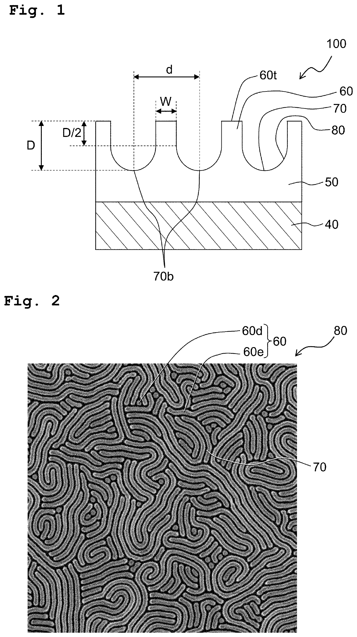
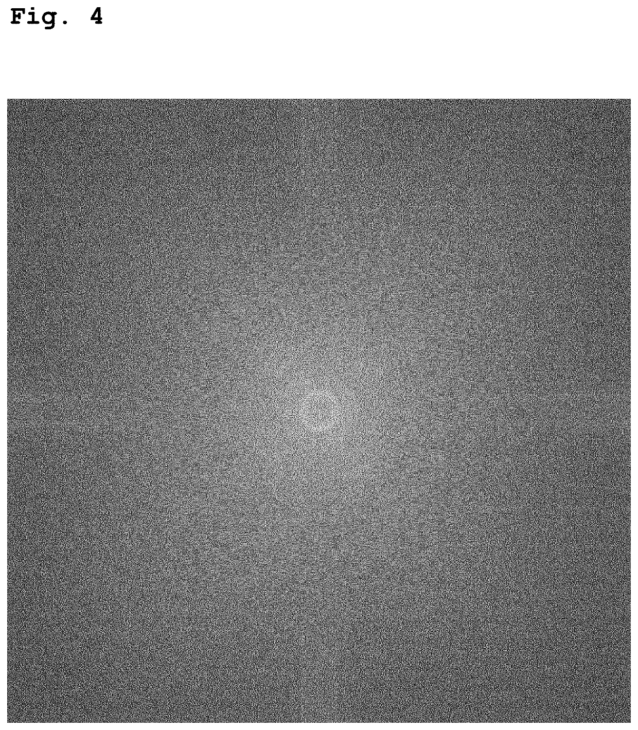
An antifogging member has an concave-convex surface defined by convex portions and concave portions, a Fourier-transformed image obtained by applying two-dimensional fast-Fourier transform processing to an observation image of the concave-convex surface exhibits a circular or annular pattern having an origin for which the absolute value of the wave number is 0 μm−1 as the substantial center thereof, the convex portions and the concave portions extend in random directions in plan view, the average pitch of the concave portions and convex portions of the concave-convex surface is in the range of 50-250 nm, and the water contact angle on a smooth surface formed from the material constituting the concave-convex surface is 90 degrees or less. The antifogging member has high abrasion resistance, minimal haze, and a small difference in chromaticity and transmittance when viewed from oblique and perpendicular directions, and the transmittance and chromaticity thereof are not azimuth dependent.

Description

CROSS REFERENCE TO RELATED APPLICATION[0001]This application is a continuation application of International Patent Application No. PCT / JP2018 / 020775 filed on May 30, 2018 claiming the benefit of priority of Japanese Patent Application No. 2017-108305 filed on May 31, 2017. The contents of International Patent Application No. PCT / JP2018 / 020775 and Japanese Patent Application No. 2017-108305 are incorporated herein by reference in their entities.BACKGROUND OF THE INVENTIONField of the Invention[0002]The present invention relates to an antifogging member.Description of the Related Art[0003]Transparent base materials, such as inorganic glass, are conventionally used for optical members, such as window members and mirrors for buildings, industries, and automobiles, glasses, goggles, camera lenses, and solar panels. If such materials are exposed to an atmosphere having high humidity, water vapor would condense into waterdrops on their surfaces. This refracts or reflects light, thus deteri...

Claims


Application Information

Patent Timeline
IPC IPC(8): G02B1/18B29C59/02
CPCB32B3/30G02B1/18B32B7/023B32B27/08B29C59/02B29C2059/023G02B27/0006G02B1/10Y10T428/24612Y10T428/24479Y10T428/26
Inventor TAKESHITA, AYANOTAKANO, KAORITAKAHASHI, MADOKASEKI, TAKASHI
Owner ENEOS CORP
Learn More