Gear rod rotator systems

Active Publication Date: 2020-01-16
NORRIS RODS INC
View PDF2 Cites 1 Cited by
  • Summary
  • Abstract
  • Description
  • Claims
  • Application Information

AI Technical Summary

Benefits of technology

The present patent relates to gear rod rotator systems and top caps for gear rod rotators. The technical effects of the patent include improved gear rod rotator systems with a top cap that can be easily mounted onto a polished rod, as well as a system for determining the status of the reciprocating rod. The top cap can include a sensor mounting port hole and a sensor module to monitor and control the system for extracting organic compounds from natural sources. The gear rod rotator systems can include a central housing with a ratchet mechanism and a top cap rotating mechanism, as well as a linkage to connect the top cap to the top cap rotating mechanism. The gear rod rotator systems can also include a computer processor and a display system for monitoring and controlling the system.

Problems solved by technology

Therefore, crude oil in such wells can rise to the well surface without any assistance.
But, even though an oil well can initially produce on its own, natural pressure generally declines as the well ages.
Reciprocation of the sucker rod string in deviated wells within the sucker rod pump system often leads to uneven frictional wear on the surface of sucker rod pump components such as the sucker rod, tubing, guide, and coupling.
Uneven wear of the components leads to costly maintenance and repairs.
However, even though rod rotators may prolong the life of sucker rod pump system components, contemporary rod rotators eventually fail to rotate in deviated wells that have high torsional drag due to the excessive contact of the rod string and the tubing and such failures lead to oil well production interruptions.

Method used


Image

  • Gear rod rotator systems
  • Gear rod rotator systems
  • Gear rod rotator systems

Examples


example 1

ve Gear Rotator System Specifications

[0139]In table 1, a comparative gear rod system not having a nesting region (“Comparative SGR”) is compared to a gear rod system having a nesting region or locking fixture (“SGR w / Nesting region”). Besides an over four times greater maximum output torque, the SGR w / nesting region has a 90° lever pulls per revolution of 200 (or a rotation speed of 200 lever pulls per rod revolution), or 45° lever pulls per revolution of 400 (or a rotation speed of 400 lever pulls per rod revolution), which is greater than the Comparative SGR value of from 144-154.

TABLE 1Comparison of Comparative SGR to SGR w / Nesting RegionSGR w / NestingMetricComparative SGRRegion90 Lever pulls per144-154200revolutionPolished rod clampFriction forceTop Cap Polishedtorque transmissionRod Clamp, NestingRegion and DirectGear Torque-driven SystemMaximum output240 (depending on the1219 regardlesstorque (ft. / lbs.)polished rod load andof the polishedrating of the gear teeth)rod loadMaxim...


PUM


Abstract

The disclosure is directed to top caps for gear rod rotators and polished clamps. Disclosed top caps include an elongated top cap body extending along a central vertical axis, the top cap body including a top face, a bottom face, and an exterior perimeter surface defining an outer perimeter of the top cap body, and a polished rod opening extending along the central vertical axis of the top cap body, the polished rod opening defining an interior circumferential surface of the top cap body and configured to receive a polished rod. Additionally, disclosed top caps include a nesting region along the top face, the nesting region configured to receive at least a portion of the polished rod clamp, and a mounting rim on the bottom face and extending outwardly from the bottom face along a longitudinal axis of the top cap body, the mounting rim including a mounting rim outer diameter, a mounting rim inner diameter, and a mounting rim bottom face. Disclosed top caps also include a top cap sensor mounting port hole configured to receive a top cap sensor module comprising a sensor including a position sensor, a temperature sensor, and a vibration sensor.

Description

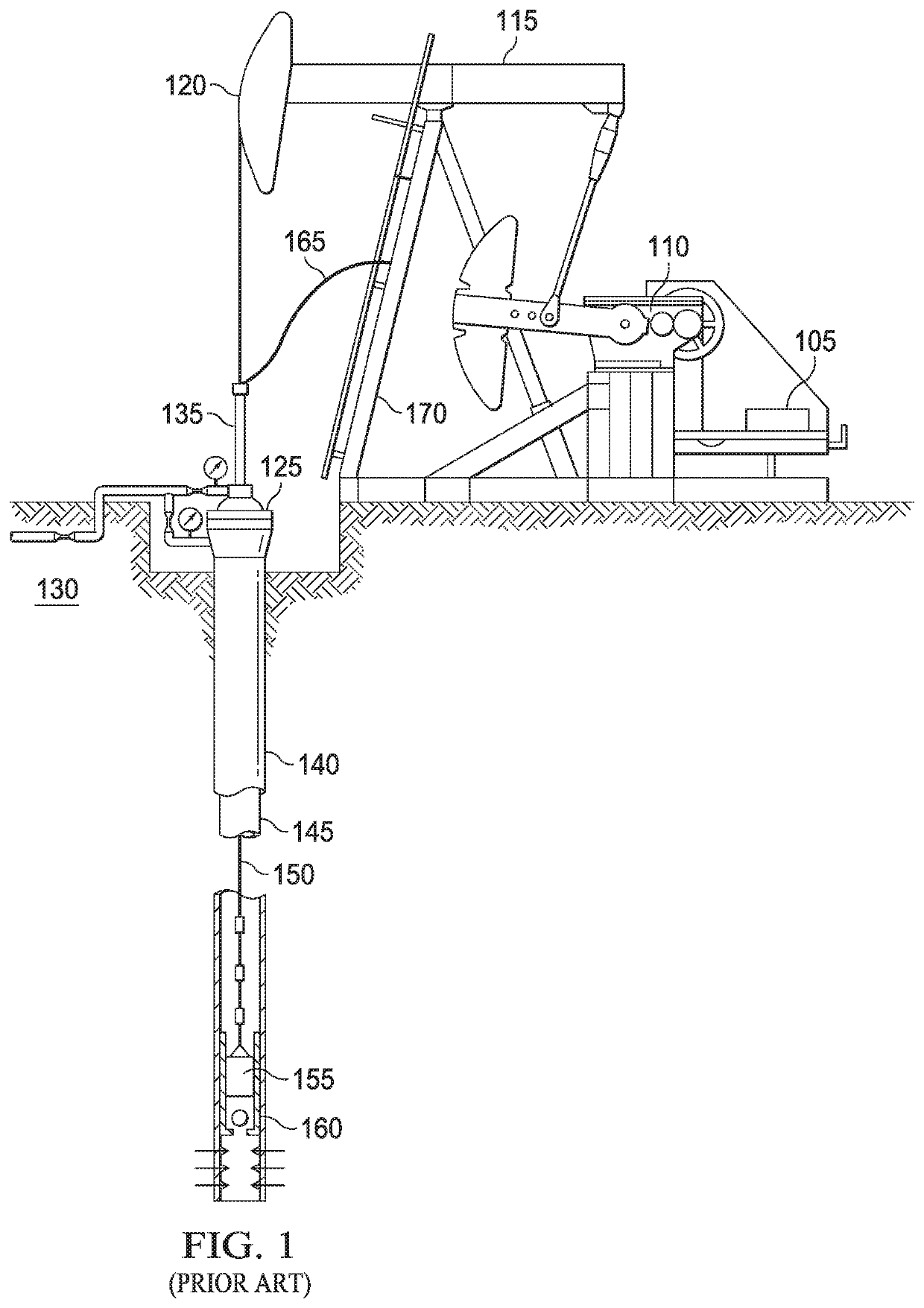
CROSS-REFERENCE TO RELATED APPLICATIONS[0001]This application claims priority to U.S. Provisional Patent Application No. 62 / 697,784 filed on Jul. 13, 2018. The contents of the above application are hereby incorporated in its entirety by reference.FIELD OF THE DISCLOSURE[0002]The present disclosure relates, in some embodiments, to rod rotator systems for positive drive rotating a string of reciprocating sucker rods during the operation of oil pumping equipment for deviated wells in the oil and gas industry.BACKGROUND OF THE DISCLOSURE[0003]Upon completion of drilling an oil well, fluids from the oil well may be under sufficient innate or natural pressure to allow the oil well to produce on its own. Therefore, crude oil in such wells can rise to the well surface without any assistance. But, even though an oil well can initially produce on its own, natural pressure generally declines as the well ages. In many oil wells, therefore, fluids are artificially lifted to the surface with down...

Claims


Application Information

Patent Timeline
IPC IPC(8): E21B17/10E21B47/09E21B47/06
CPCF04B47/026E21B47/09E21B17/1071E21B47/065E21B43/127E21B47/07
Inventor CORTES, PABLO E. BARAJASCASEY, WANRUNARASIMHAN, RAMAMURTHYWALLACE, JACK LYNNPUGLIESE, JUAN FELIPE CORREA
Owner NORRIS RODS INC
Why Eureka
Try Eureka