
Methods & apparatus for controlling an industrial process

a technology of industrial process and control method, applied in the field of lithographic process, can solve the problems of imposing a particular error “fingerprint” on the product, loss of performance, and current control system not being adapted to use this different context to allow effective per-wafer control, and achieve the effect of reliable performance improvemen

Pending Publication Date: 2020-02-13
ASML NETHERLANDS BV
View PDF1 Cites 6 Cited by
  • Summary
  • Abstract
  • Description
  • Claims
  • Application Information

AI Technical Summary

Benefits of technology

The invention aims to improve monitoring and control of industrial processes, particularly in lithographic manufacturing processes, by using statistical analysis to select representative product units or by grouping wafers and selecting samples from each group. This helps to maintain accuracy of control and improve performance without adding excessive metrology overhead. The technical effect is improved accuracy and control in industrial processes, particularly in lithographic manufacturing processes.

Problems solved by technology

The accurate placement of patterns on the substrate is a chief challenge for reducing the size of circuit components and other products that may be produced by lithography.
Each of these tools can impose a particular error “fingerprint” on the products.
Combining different lots into the same threads without sufficient regard to their different contexts will cause loss of performance also.
Different wafers within a lot may in practice have different contexts, but current control systems are not adapted to use this different context to allow effective per-wafer control.
A significant overhead in any advanced process control system is the number of measurements required to provide meaningful feedback and / or feedforward corrections.

Method used


Image

  • Methods & apparatus for controlling an industrial process
  • Methods & apparatus for controlling an industrial process
  • Methods & apparatus for controlling an industrial process

Examples


Embodiment Construction

[0038]Before describing embodiments of the invention in detail, it is instructive to present an example environment in which embodiments of the present invention may be implemented.

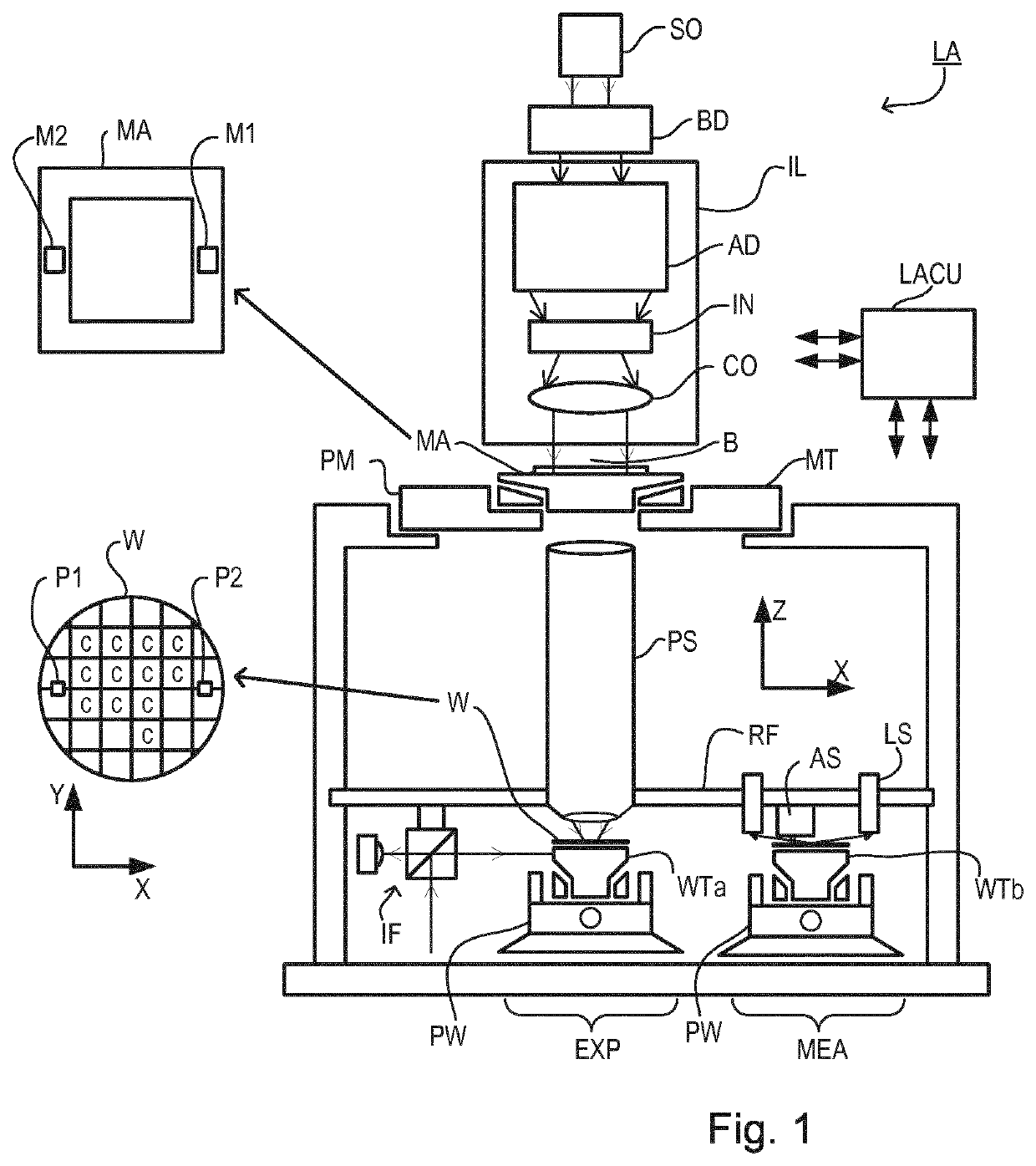
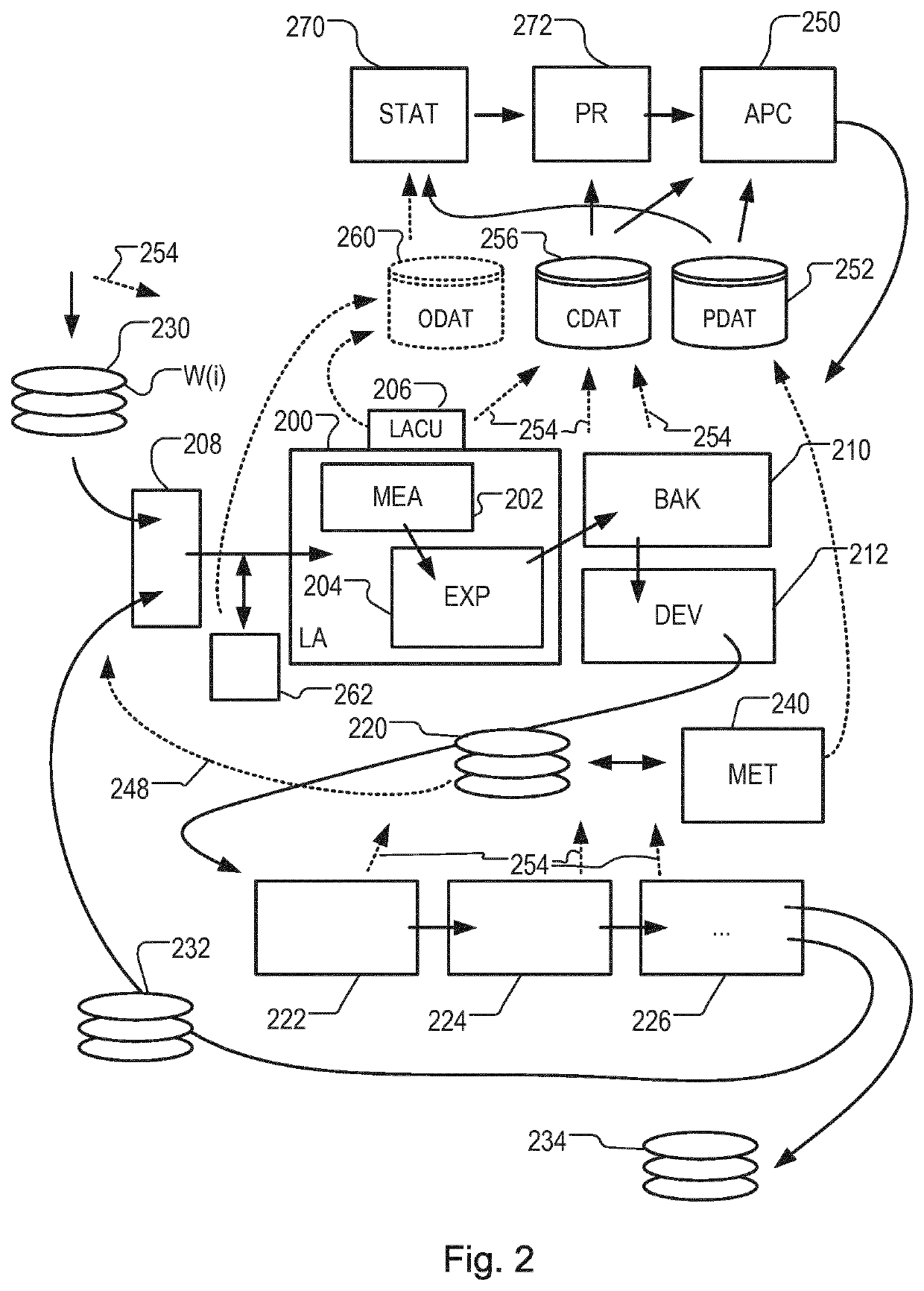
[0039]FIG. 1 schematically depicts a lithographic apparatus LA. The apparatus includes an illumination system (illuminator) IL configured to condition a radiation beam B (e.g., UV radiation or DUV radiation), a patterning device support or support structure (e.g., a mask table) MT constructed to support a patterning device (e.g., a mask) MA and connected to a first positioner PM configured to accurately position the patterning device in accordance with certain parameters; two substrate tables (e.g., a wafer table) WTa and WTb each constructed to hold a substrate (e.g., a resist coated wafer) W and each connected to a second positioner PW configured to accurately position the substrate in accordance with certain parameters; and a projection system (e.g., a refractive projection lens system) PS configured t...


PUM

PropertyMeasurementUnit
wavelengthaaaaaaaaaa

Abstract

A lithographic process is performed on a plurality of semiconductor substrates. The method includes selecting one or more of the substrates as one or more sample substrates. Metrology steps are performed only on the selected one or more sample substrates. Based on metrology results of the selected one or more sample substrates, corrections are defined for use in controlling processing of the substrates or of future substrates. The selection of the one or more sample substrates is based at least partly on statistical analysis of object data measured in relation to the substrates. The same object data or other data can be used for grouping substrates into groups. Selecting of one or more sample substrates can include selecting substrates that are identified by the statistical analysis as most representative of the substrates in their group and / or include elimination of one or more substrates that are identified as unrepresentative.

Description

CROSS-REFERENCE TO RELATED APPLICATIONS[0001]This application claims priority of EP application 16195049.8 which was filed on Oct. 21, 2016 and which is incorporated herein in its entirety by reference.BACKGROUNDRelated Art[0002]A lithographic process is one in which a lithographic apparatus applies a desired pattern onto a substrate, usually onto a target portion of the substrate, after which various processing chemical and / or physical processing steps work through the pattern to create functional features of a complex product. The accurate placement of patterns on the substrate is a chief challenge for reducing the size of circuit components and other products that may be produced by lithography. In particular, the challenge of measuring accurately the features on a substrate which have already been laid down is a critical step in being able to position successive layers of features in superposition accurately enough to produce working devices with a high yield. So-called overlay ...

Claims


Application Information

Patent Timeline
Patent Type & Authority Applications(United States)
IPC IPC(8): G05B19/418
CPCG05B2219/2602G05B2219/45031G05B2219/42001G05B2219/32191G05B19/4188G05B19/41875G05B2219/32206G05B2219/37224G03F7/70525Y02P90/02G05B19/4183G05B19/41885
Inventor KOU, WEITIANYPMA, ALEXANDERHAUPTMANN, MARCKUPERS, MICHIELHAN, MIN-SUB
Owner ASML NETHERLANDS BV
Learn More