Lithium Ion Battery and Prelithiation Method of Anode

Pending Publication Date: 2020-02-27
ROBERT BOSCH GMBH
View PDF2 Cites 1 Cited by
  • Summary
  • Abstract
  • Description
  • Claims
  • Application Information

AI Technical Summary

Benefits of technology

The present disclosure introduces a prelithiation method that can compensate for capacity fading and significantly improve battery performances like reversible capacity and cycling stability. Unlike external lithium metal, this method is easy, safe, cost-effective, and labor-saving as it realizes in-situ prelithiation without requiring a special assembly condition.

Problems solved by technology

However, the moving lithium ions inevitably and continuously react with electrolytes.
As a result, lithium is undesirably consumed and solid electrolyte interfaces (SEI) are formed on the anodes.
The consumed lithium does not return to the cathodes during subsequent discharges, causing fast capacity fading for the lithium ion batteries.
However, due to the high activity of the prelithiated anode, the battery production procedures following the prelithiation step require an operating environment with well-controlled humidity, which increases the manufacturing cost of lithium ion batteries.

Method used


Image

  • Lithium Ion Battery and Prelithiation Method of Anode

Examples


example 1

on of a Cell

Preparation of a Cathode

[0066]At room temperature, 965 gNCM-111, 15 g Super P and 20 g PVDF were added into 300 g NMP in a 1 L round bottom flask equipped with a stirrer. After stirring for 3 h, the resultant uniformly-dispersed slurry was coated onto an aluminum foil, then dried at 80° C. for 6 h. The coated Al foil was cut into several Φ12 mm cathodes.

Preparation of an Anode

[0067]At room temperature, 40 g Si powders, 40 g graphite powders, 10 g LiPAA, 2 g Super P and 2 g KS6L were added into 100 g deionized water in a 500 mL round bottom flask equipped with a stirrer. After stirring for 3 h, the resultant uniformly-dispersed slurry was coated onto a copper foil, then dried at 60° C. for 6 h. The coated Cu foil was cut into several Φ12 mm anodes.

Preparation of a Cell

[0068]Coin cells (CR2016) were assembled in an Argon-filled glovebox (MB-10 compact, MBraun) by using the cathodes and anodes obtained above. 1M LiPF6 in FEC / EC / EMC (30:35:35 by volume) was used as an electr...

example 2 (

Ex. 2)

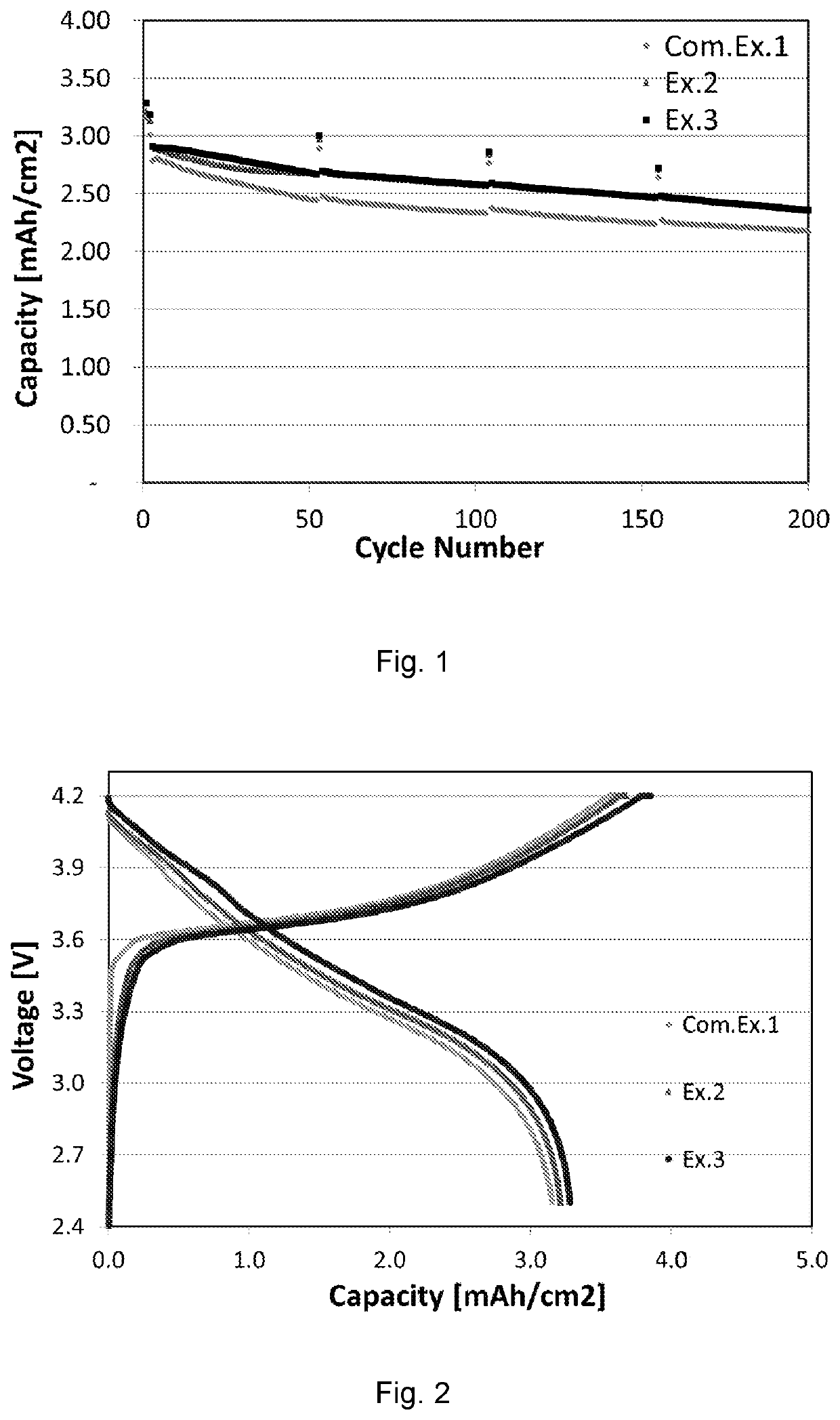
[0070]A coin cell obtained in Example 1 was placed into a temperature chamber (VT 3050, available from Voetsch). The temperature was raised to 45° C. and kept for 5 hours. Then the cell was charged at 45° C. to 4.2 V (vs Li / Li+) at a current of 0.1 C for the 1st charge cycle. Subsequently, the cell was taken out of the temperature chamber and cooled down to room temperature (25° C.). Then the cell was discharged at 25° C. to 2.5 Vat a current of 0.1 C for the 1st discharge cycle. The aforementioned charge / discharge cycles was repeated in the 2nd and 3rd cycles. During the 4th to 200th cycles, the cell was charged / discharged at 25° C. within a normal voltage range from 2.5 to 4.2V at a current of 0.5 C. The mass loading of NCM in each cathode of the cells is about 10 mg / cm2. The specific capacities were calculated on the basis of the weight of NCM.

example 3 (

Ex. 3)

[0071]A coin cell was charged / discharged in the way as described above for Example 1, except that before charging, the temperature was raised to 65° C. and kept for 5 hours. Then the cell was charged at 65° C. to 4.2 V (vs Li / Li+) at a current of 0.1 C during the 1st to 3rd charge cycles.


PUM


Abstract

A method for prelithiating an anode of lithium ion batteries includes the following steps: (a) charging the battery to a voltage from about 4.2 to about 4.5 V at a first temperature; and (b) discharging the battery to a voltage from about 2.5 to about 3.2 V at a second temperature which is about 20 to 40° C. lower than the first temperature. Also provided is a lithium ion battery having an anode prelithiated by the method.

Description

TECHNICAL FIELD[0001]The present invention relates to a lithium ion battery and a method for prelithiating an anode of lithium ion batteries.BACKGROUND[0002]Lithium ion batteries have now been widely used in energy storage systems and electric vehicles.[0003]For lithium ion batteries which comprise lithium-containing cathode materials (such as LiCoO2 or LiNiO2), lithium ions move from cathodes to anodes when charging. However, the moving lithium ions inevitably and continuously react with electrolytes. As a result, lithium is undesirably consumed and solid electrolyte interfaces (SEI) are formed on the anodes. The consumed lithium does not return to the cathodes during subsequent discharges, causing fast capacity fading for the lithium ion batteries.[0004]It has been proposed to pre-intercalate lithium from external lithium metal into a coated anode tape so as to prelithiate the anode and compensate the capacity fading. The prelithiated anode is subsequently assembled into a lithium...

Claims


Application Information

Patent Timeline
IPC IPC(8): H01M10/0525H01M10/44H01M4/134H01M4/133
CPCH01M4/134H01M10/44H01M4/133H01M10/0525H01M10/446H01M10/049H01M4/587H01M4/386H01M10/443Y02E60/10Y02P70/50H01M4/139H01M4/1395H01M4/1393H01M4/1391H01M4/0459H01M4/0445H01M10/052H01M2004/027
Inventor HAO, XIAOGANGJIANG, RONGRONG
Owner ROBERT BOSCH GMBH
Why Eureka
Try Eureka