

Porous silicon based anode material formed using metal reduction
a technology of porous silicon and anode material, which is applied in the direction of silicon compounds, cell components, paper/cardboard articles, etc., can solve the problems of reducing the cycling efficiency, structural integrity of the electrode, and unsuitable commercially high-capacity negative electrode materials
- Summary
- Abstract
- Description
- Claims
- Application Information
AI Technical Summary
Benefits of technology
Problems solved by technology
Method used
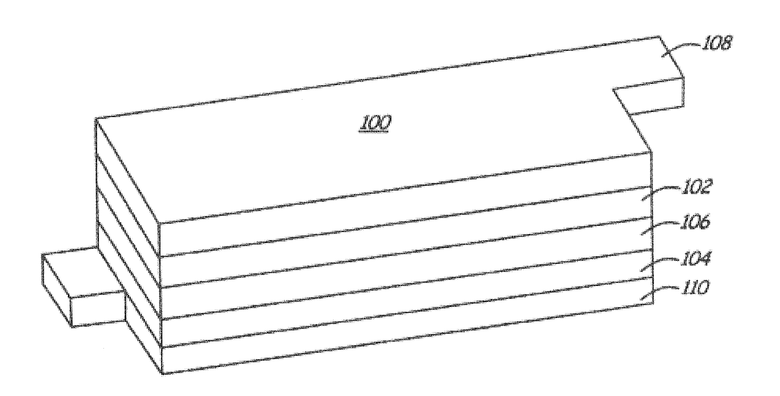
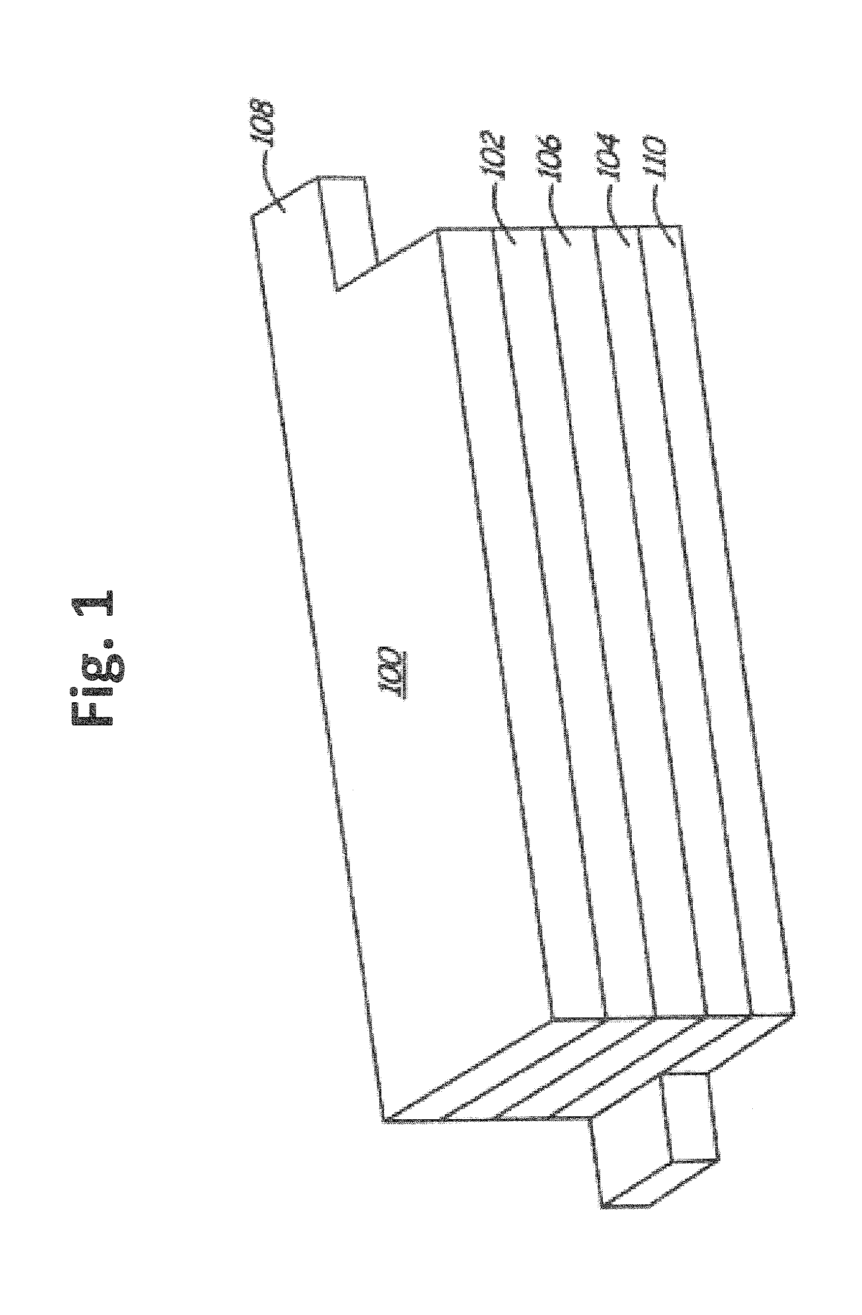
Image

Examples
example 1
Formation of Porous Silicon Based Material Using Magnesium Reduction
[0108]This example demonstrates the effective synthesis of the porous silicon using magnesium metal to reduce silicon dioxide and the characterization of the product material.
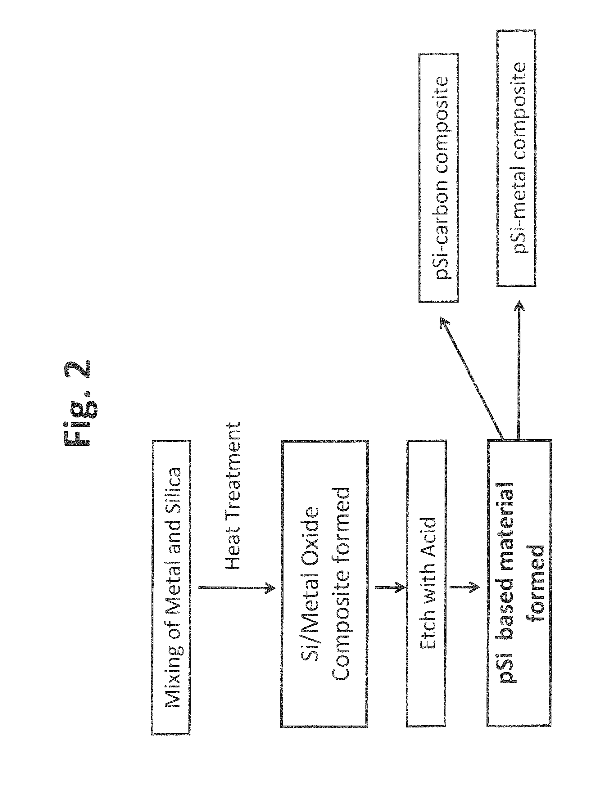
[0109]In particular, a solid state metal reduction process using a reducing agent such as Mg metal to reduce silica (SiO2) to silicon followed by acid leaching to remove the metal was used to produce porous silicon based material. The process is described in FIG. 2. Specifically, in the first step, commercially available silica and magnesium powder were intimately mixed using a high energy ball mill at for about 15 min to 10 h. The mixed sample was then taken in an alumina crucible and heat treated in a tube furnace under Ar atmosphere. During the heat treatment process, magnesium reduced silica into silicon and magnesium was oxidized to form magnesium oxide (MgO). The MgO and any unreacted Mg metal were subsequently removed by chemical etching...
example 2
Cycling Performance of Batteries Formed from the Porous Silicon Material with a Lithium Metal Counter Electrode
[0113]This example demonstrates superior performance of the porous silicon materials in batteries with a lithium foil counter electrode. The porous silicon materials formed under the conditions summarized in Table 1 and as described in Example 1 above was used to construct correspondingly numbered batteries with a lithium metal counter electrode. The general formation of the batteries is described in detail above. The first cycle lithium deintercalation capacities of the batteries are listed in table 1 and the electrochemical performances of the batteries are shown in FIG. 6a. With the exception of sample 5, the porous silicon produced at 2° C. / min ramp rate, all the batteries cycled well showing high capacity and good cycle life up to 55 cycles. Of the samples examined, battery 7 formed with sample 7 porous silicon exhibited the best cycling performance, and battery 6 form...
example 3
Cycling Performance of Batteries Formed from Carbon Composites of Porous Silicon with a Lithium Metal Counter Electrode
[0115]This example demonstrated that the performance of composite material formed from the porous silicon and carbon can reduce the irreversible capacity loss and stabilize the cycling.
[0116]The first cycle capacity losses (IRCL) of porous silicon samples from example 1 are summarized in Table 1. To examine the effects of forming composites with carbon, silicon carbon composites were formed using the porous silicon from sample 6 (pSi). A first set of composite samples were prepared with pyrolytic carbon coated on the surface of the porous silicon of sample to form a hard carbon and porous silicon composite (pSi-C) by a hydrothermal approach using glucose as the carbon source. Specifically, glucose was dissolved in water and mixed with the pSi material. The solution was then ultrasonically mixed. The obtained solution was transferred to a Teflon® vessel and hydrother...
PUM
 Abstract
Description
Claims
Application Information