Sulfur-carbon nanocomposites and their application as cathode materials in lithium-sulfur batteries

a lithium-sulfur battery and carbon nanocomposite technology, applied in the direction of non-aqueous electrolyte cells, cell components, electrochemical generators, etc., can solve the problems of poor electrochemical contact of sulfur, low utilization of active materials in the cathode, and the low implementation of the lithium-sulfur system in high-power applications. to achieve the effect of minimizing the formation of lithium sulfid

Active Publication Date: 2011-03-03
UT BATTELLE LLC
View PDF14 Cites 149 Cited by
  • Summary
  • Abstract
  • Description
  • Claims
  • Application Information

AI Technical Summary

Benefits of technology

[0011]In one aspect, the invention is directed to a sulfur-carbon (S / C) composite material useful as a cathodic material in a lithium-sulfur battery. Special design features have been incorporated into the sulfur-carbon composite material that permits the composite material to substantially minimize the formation of lithium sulfide at the anode.

Problems solved by technology

Nevertheless, the Li / S system has not yet been implemented in high power applications because of two significant obstacles: the poor electrical conductivity of elemental sulfur and the intrinsic polysulfide shuttle.
The electrical conductivity of elemental sulfur is as low as 5×10⁻³ S / cm at 25° C. Such a low conductivity causes poor electrochemical contact of the sulfur and leads to low utilization of active materials in the cathode.
The concentration gradients of the polysulfide species drive the intrinsic polysulfide shuttle between the electrodes, and this leads to poor cyclability, high current leakage, and low charge-discharge efficiency.
This deposition process occurs in each charge / discharge cycle and eventually leads to the complete loss of capacity of the sulfur cathode.
However, protection of the lithium anode leads to the passivation of the anode, and this in turn causes a slow reaction rate of the anode during the discharge cycle.
Therefore, protection of the lithium anode leads to the loss of power density.
However, the slow transport of ions leads to a low power density.
Moreover, neither the protection of lithium anode nor the restraining of ionic mobility completely shuts down the polysulfide shuttle.
Although the polysulfide shuttle occurs at slow speed, such modified Li / S batteries generally suffer from a significantly shortened lifespan as compared to lithium ion batteries without these modifications.

Method used


Image

  • Sulfur-carbon nanocomposites and their application as cathode materials in lithium-sulfur batteries
  • Sulfur-carbon nanocomposites and their application as cathode materials in lithium-sulfur batteries
  • Sulfur-carbon nanocomposites and their application as cathode materials in lithium-sulfur batteries

Examples


example 1

Preparation of the Bimodal Porous Carbon Material (a-MPC) and Treatment Thereof to Form the Sulfur-Carbon Composite

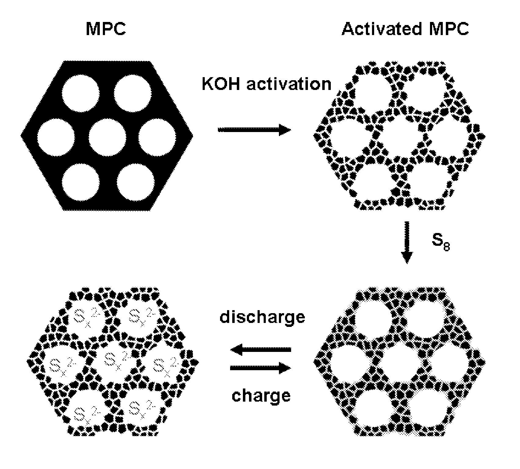
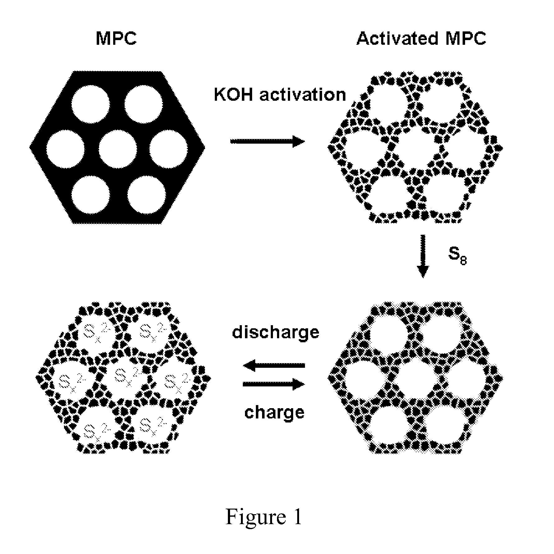
[0064]The general procedure for preparing the sulfur-carbon composite is shown in FIG. 1. FIG. 1 also depicts the change in arrangement of sulfur in the bimodal carbon material during charging and discharging steps.

[0065]Preparation of bimodal porous carbon material (a-MPC). The Precursor mesoporous carbon (MPC) was synthesized through a previously reported soft-template approach (Wang, X. Q.; Liang, C. D.; Dai, S. Langmuir 2008, 24, 7500-7505; Liang, C. D.; Dai, S. Journal of the American Chemical Society 2006, 128, 5316-5317; and Liang, C. D.; Hong, K. L.; Guiochon, G. A.; Mays, J. W.; Dai, S. Angewandte Chemie-International Edition 2004, 43, 5785-5789). The MPC has a uniform mesopore distribution at ca. 7.3 nm, an average wall thickness of about 6 nm, a specific Brunauer-Emmett-Teller (BET) surface area of 368.5 m2 / g, and a pore volume of 0.56 cm3 / g.

[0066]The MPC was...

example 2

Analysis of the Sulfur-Carbon Composite

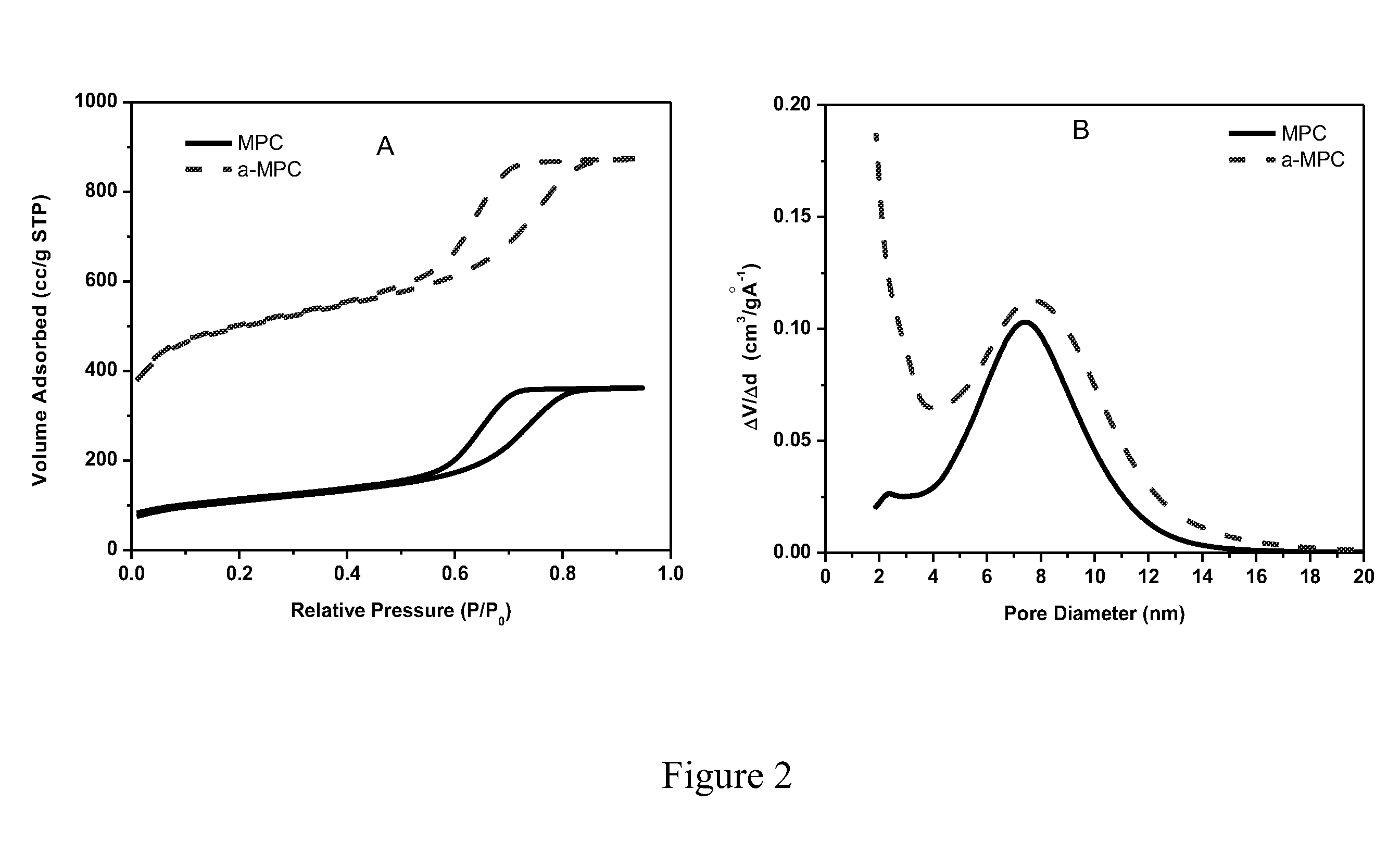
[0068]The surface area (SA) and pore size distribution (PSD) of the S / C composites produced as described in Example 1 were analyzed through N2 adsorption / desorption measurements at 77 K and plotted in FIGS. 4 (A and B). The N2 isotherms of these samples have a capillary condensation step centered at relative pressure (P / P0) of 0.7 and a H1 type hysteresis. The samples S_C01 to S_C05 have a bimodal pore size distribution with mesopores averaged at 7.3 nm. The cumulative pore volume (FIG. 4C) of samples with sulfur loading less than 37.1 wt. % shows an upward inflection point at pore diameter of 3 nm. Therefore, a portion of the pore volume and surface area of samples with sulfur loading less than 37.1 wt. % are attributed to small mesopores (pore size <3 nm) and micropores. FIG. 4D illustrates the dependence of pore volume and surface area on sulfur loading. The micropore volume was completely filled up when the sulfur loading is above 37.1 wt. ...

example 3

Assembly of Lithium-Sulfur Batteries

[0069]The S / C composites, prepared as described above, were pulverized by a ball mill and sieved through a 25 μm-opening stainless steel sieve. Slurries were prepared by mixing the S / C composites in a solution of 1 wt. % poly(vinylidene fluoride) (PVDF) in anhydrous N-methyl-2-pyrolidinone (NMP) in a 1:5 ratio. The slurries were applied to 10 mm diameter aluminum current collectors and dried at 120° C. for 4 hours. For the purpose of comparison, the original mesoporous carbon (MPC) with 24.1 wt. % sulfur loading and WVA-1500 (MeadWestvaco Corporation) with sulfur loading of 25.2 wt. % were also prepared as cathodes according to the same procedure used for the preparation of S / C composite cathodes. The batteries were assembled as Swagelok cells by using the S / C composite coated aluminum foil (10 mm diameter, 7 mm thick) as the cathode, and a lithium foil (7 mm thick and 10 mm diameter) as the anode, a Celgard 3225 separator (10.3 mm diameter), and ...


PUM

PropertyMeasurementUnit
conductivityaaaaaaaaaa
pore sizeaaaaaaaaaa
pore sizeaaaaaaaaaa

Abstract

The invention is directed in a first aspect to a sulfur-carbon composite material comprising: (i) a bimodal porous carbon component containing therein a first mode of pores which are mesopores, and a second mode of pores which are micropores; and (ii) elemental sulfur contained in at least a portion of said micropores. The invention is also directed to the aforesaid sulfur-carbon composite as a layer on a current collector material; a lithium ion battery containing the sulfur-carbon composite in a cathode therein; as well as a method for preparing the sulfur-composite material.

Description

CROSS REFERENCE TO RELATED APPLICATION[0001]This application claims the benefit of priority from U.S. Provisional Application No. 61 / 239,132, filed on Sep. 2, 2009, the content of which in its entirety is incorporated herein by reference.[0002]This invention was made with government support under Contract Number DE-AC05-00OR22725 between the United States Department of Energy and UT-Battelle, LLC. The U.S. government has certain rights in this invention.FIELD OF THE INVENTION[0003]The present invention relates generally to cathode materials for lithium ion batteries, and more particularly, cathode materials for lithium-sulfur batteries.BACKGROUND OF THE INVENTION[0004]Lithium-ion batteries have found widespread usage as electrical energy storage devices in various portable electronics because of their light weight relative to other types of batteries. However, particularly for high power applications such as electric vehicles, there has been a continuing effort to improve the energy...

Claims


Application Information

Patent Timeline
Patent Type & Authority Applications(United States)
IPC IPC(8): H01M4/583H01M10/05B05D5/12H01M10/056H01M10/26
CPCC01B31/12Y02E60/122H01M4/1393H01M4/1397H01M4/362H01M4/364H01M4/581H01M4/5815H01M4/587H01M4/625H01M10/052H01M10/0565H01M10/0566H01M10/0567H01M10/0569H01M4/136C01B32/342Y02E60/10H01M4/0402H01M4/0416H01M4/0471H01M4/133H01M2004/021Y02T10/70
Inventor LIANG, CHENGDUDUDNEY, NANCY J.HOWE, JANE Y.
Owner UT BATTELLE LLC
Why Eureka
Try Eureka