
Electric machine

a technology of electric machines and cooling systems, applied in the direction of dynamo-electric machines, electrical apparatus, electrical apparatus contruction details, etc., can solve the problems of relatively high losses, dispersal of heat produced by electronic modules during the operation of electric machines, and cooling systems of electronic components. achieve the effect of increasing reliability

Active Publication Date: 2020-03-05
SPAL AUTOMOTIVE
View PDF0 Cites 1 Cited by
  • Summary
  • Abstract
  • Description
  • Claims
  • Application Information

AI Technical Summary

Benefits of technology

The invention is about a rotary electric machine that better dissipates heat generated inside, especially by the electronic control module. This improves reliability. The machine uses a MOSFET to prevent short circuits between the heat transfer device and the heat sink. Compared to previous heat joint solutions, the invention eliminates thermal resistance between the MOSFET and the heat transfer device, improving the performance of the electronic module in terms of heat discharge. The heat transfer device allows most of the heat to be drawn off and transferred to the cap of the machine, preventing overheating. The heat transfer devices have high thermal conductivity, allowing the heat to be efficiently exchanged with the machine cap.

Problems solved by technology

One of the principle difficulties in the above-mentioned electric machines, in particular in those of the “sealed” type, is the dispersal of the heat produced by the electronic module during operation of the electric machine.
However, despite the relatively low internal resistance of the electronic power components the circulating currents in the electronic power components can cause relatively high losses due to the Joule effect.
In these circumstances, the cooling system of the electronic components such as, for example, described in patent application WO2014125412 could be insufficient to guarantee the expected performance.
In fact, the heat generated by the MOSFETs, as already mentioned, must flow through the tab and the flap to the heat transfer device: in the case of high heat development, in particular with thinned tabs and, possibly, without a flap (in which case it is not possible to effectively connect the heat transfer device to the respective MOSFET), the overall temperature of the electronic module could rise above the limits to optimum operating limits.

Method used


Image

  • Electric machine
  • Electric machine
  • Electric machine

Examples


Embodiment Construction

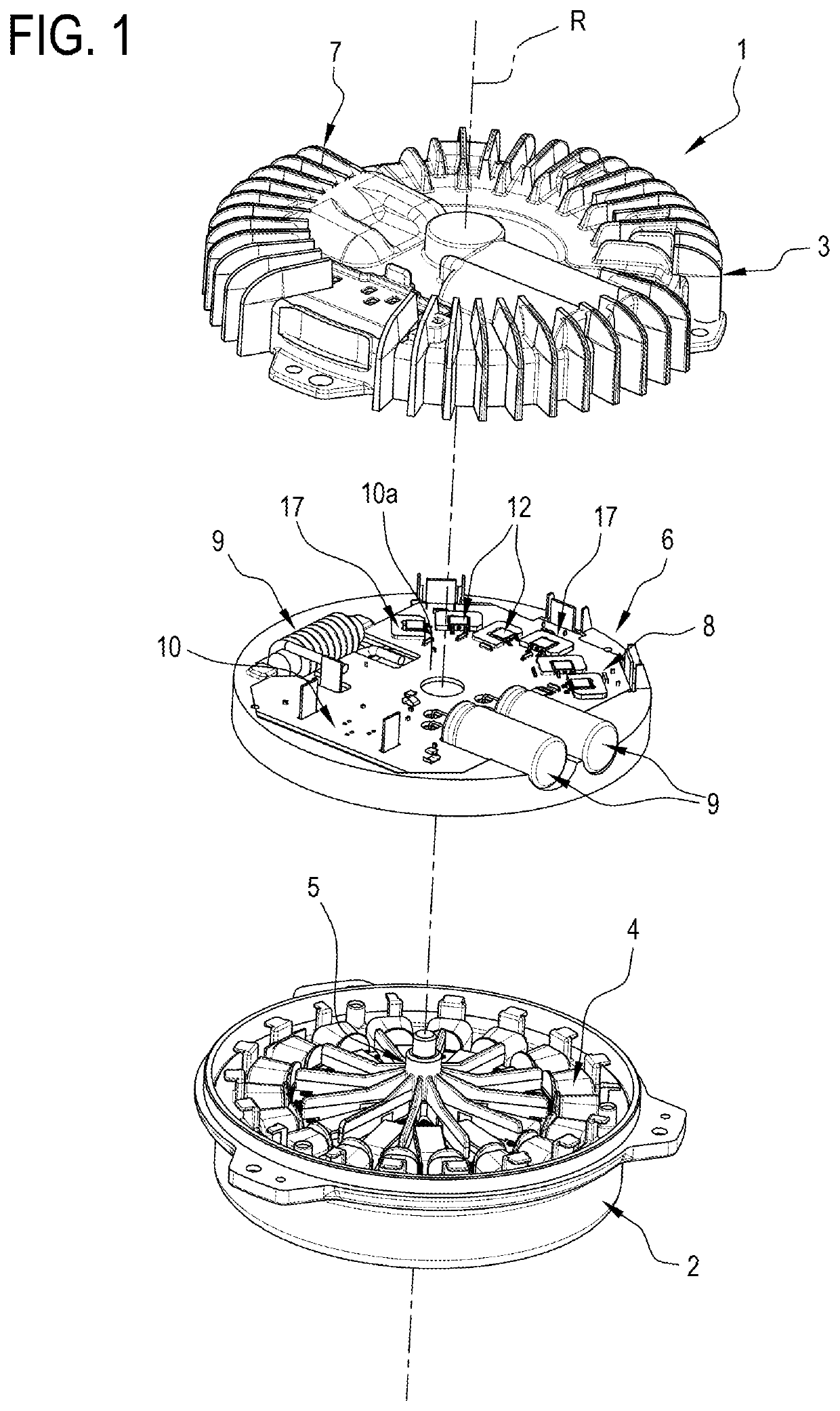
[0076]With particular reference in particular to FIG. 1, the numeral 1 denotes a rotary electric machine according to at least one aspect of the invention.

[0077]The machine 1, in one embodiment, is an electric motor of the sealed type, that is, without any openings for access to the inside, to which express reference will hereinafter be made but without thereby limiting the scope of the invention.

[0078]The electric machine 1 will be described in detail solely for the parts necessary for the understanding of the invention.

[0079]The machine 1 comprises a casing 2 and a cap 3 for closing the casing 2 to form, with the casing 2, a case or closed container.

[0080]The electric machine 1 comprises a stator 4 fixed to the casing 2 and a rotor 5, inserted in the case, and attached to the case in a rotary manner.

[0081]The machine 1 has its own axis of rotation R around which the rotor 5 rotates.

[0082]An example of the stator 4 is described in the patent EP2215705 in the name of the same Applic...


PUM


Abstract

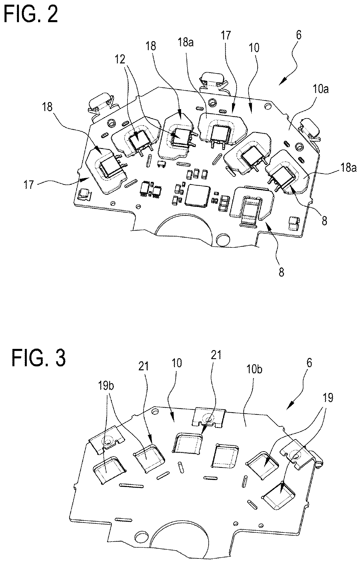
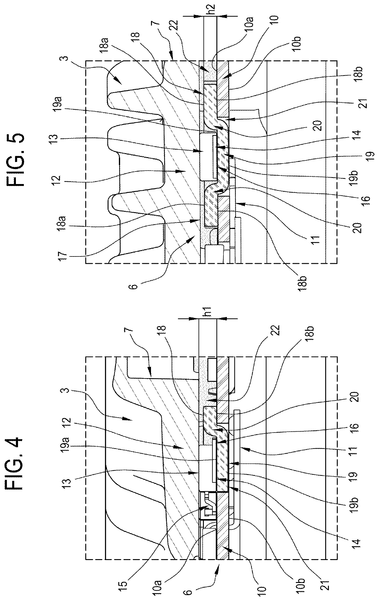
A rotary electric machine includes an electronic module and a heat sink for dissipating heat produced by the module. The module includes a printed circuit, an electronic component having a base positioned on the printed circuit, a heat transfer device connected to the printed circuit and to the electronic component for transferring heat generated by the component to the heat sink. The heat transfer device includes an upper portion extending from the printed circuit towards the heat sink from the same side of the component and a base portion connected to the upper portion and positioned in the printed circuit at least partly under the component to form, at least partly, a preferential path for the heat, from the base of the electronic component to the heat sink. The electronic component is connected at least partly by its own base to the base portion of the heat transfer device.

Description

TECHNICAL FIELD[0001]This invention relates to a rotary electric machine with reference in particular to an integrated electronic control module.[0002]In general, a rotary electric machine, for example a brushless electric motor to which reference is made hereinafter without limiting the scope of the invention, comprises a casing having inside a stator, rigidly connected to the casing, and a rotor, for example with permanent magnets, rotatably connected to the casing.BACKGROUND ART[0003]An example of a prior art electric machine used as a reference for the present patent is described in the application WO2013008180 in the name of the same Applicant.[0004]An electronic module or electronic control module, connected to the stator, comprising a printed circuit and a plurality of active and passive electronic components forming a power section and a plurality of electronic signal components forming a control section, mounted on the printed circuit.[0005]A cap closes the casing to form a...

Claims


Application Information

Patent Timeline
Patent Type & Authority Applications(United States)
IPC IPC(8): H02K11/33H01L23/367H02K11/00H02K5/18H05K1/02H01L23/40
CPCH01L23/3672H02K5/18H01L23/40H02K11/33H02K11/0094H05K1/0201H01L23/3736H01L2023/4043H01L23/367H02K2211/03H02K9/227H05K7/20509H05K7/209
Inventor DE FILIPPIS, PIETRO
Owner SPAL AUTOMOTIVE
Learn More