Method and apparatus for chromatic dispersion measurement based on optoelectronic oscillations

a technology of optoelectronic oscillation and chromatic dispersion, which is applied in the direction of measurement devices, phase-affecting property measurements, instruments, etc., can solve the problems of low accuracy, inconvenient resolution of small chromatic dispersions, time-consuming and expensive implementation,

Active Publication Date: 2020-03-26
NAT INST OF STANDARDS
View PDF10 Cites 2 Cited by
  • Summary
  • Abstract
  • Description
  • Claims
  • Application Information

AI Technical Summary

Problems solved by technology

Although the time-of-flight technique (U.S. Pat. No. 4,752,125 by Schicketanz) is simple to implement, it has low accuracy and is not suitable to resolve small chromatic dispersions.
This technique has better accuracy than the time-of-flight technique, however, it is time consuming and expensive to implement since it needs an expensive network analyzer.
Opt. Lett., (2000)); however, this technique is time-consuming due to the time required for the analysis of the acquired fringes at every wavelength.
Although further improvement has been made to this technique to make the measurement time considerably smaller (K. S. Abedin, Electronics Letters, (2005)), the chromatic dispersion measurement through voltage change degrades its accuracy and makes the traceability to the SI unit of time not easily possible.

Method used


Image

  • Method and apparatus for chromatic dispersion measurement based on optoelectronic oscillations
  • Method and apparatus for chromatic dispersion measurement based on optoelectronic oscillations
  • Method and apparatus for chromatic dispersion measurement based on optoelectronic oscillations

Examples


Embodiment Construction

[0023]The terminology used herein is for the purpose of describing particular embodiments only and is not intended to be limiting of the invention.

[0024]Novel chromatic dispersion measurement technique is discussed herein. This technique is based on the optoelectronic oscillation (OEO). In addition, a technique for compensation of the thermal fluctuations in the fiber under test by using another optoelectronic oscillator is presented.

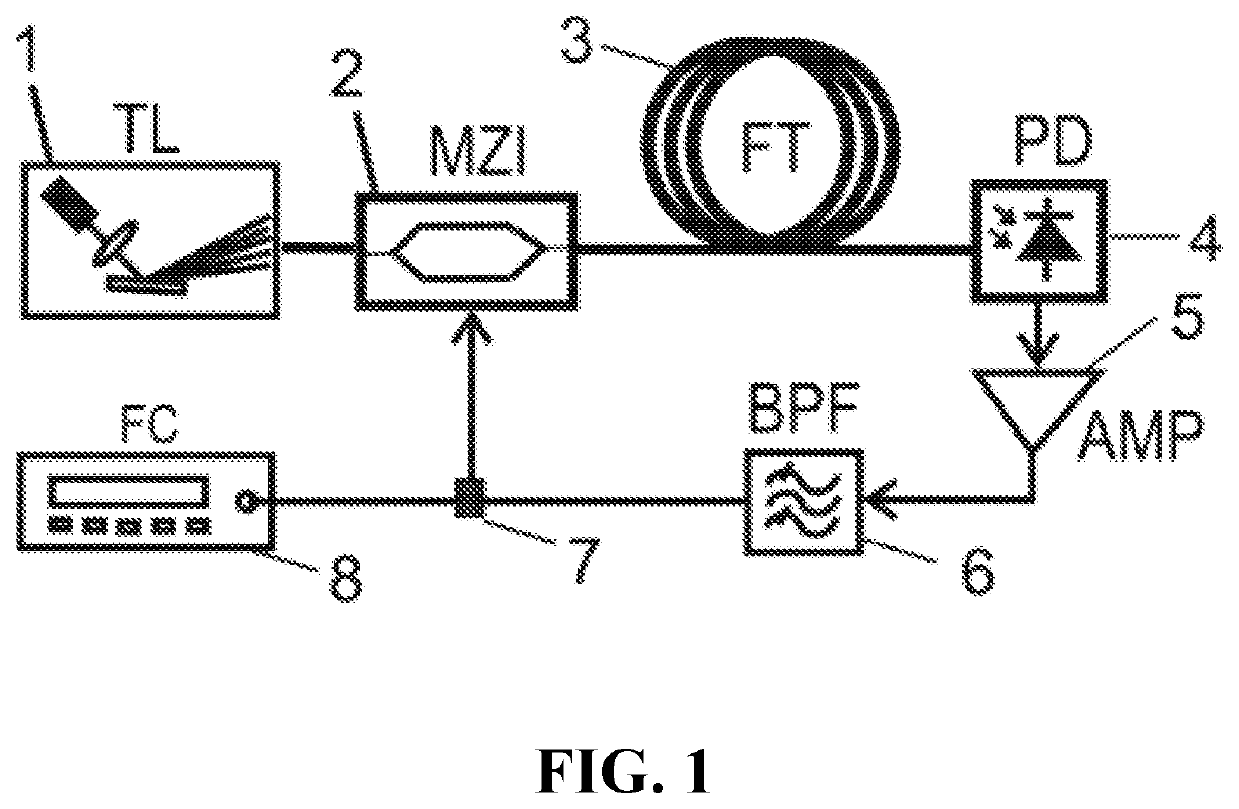
[0025]The basic oscillator comprises a tunable laser (TL) (1), an intensity modulator (MZI) (1), fiber under test (FT) (3), a photodetector (PD) (4), an amplifier (AMP) (5), a filter (BPF) (6), power splitter (7) and a frequency counter (FC)(8) which are connected as shown in FIG. 1).

[0026]The RF amplifier (5) should provide sufficient gain to compensate the loss inside the loop and therefore starting the oscillation. The basic condition for the OEO oscillation is that the accumulated phase around the loop in the optical and RF part to be integer multip...


PUM

PropertyMeasurementUnit
lengthsaaaaaaaaaa
lengthaaaaaaaaaa
lengthaaaaaaaaaa

Abstract

In this invention, a novel technique is introduced to measure chromatic dispersion (CD) in optical fibers. This technique is based on a relatively low-frequency optoelectronic oscillation (OEO) to provide fast, precise and low cost method for CD measurement that can be implemented easily in commercial instruments. In addition, another technique is presented to compensate for fiber thermal fluctuations during measurement which is based on a second simultaneously oscillating OEO. The proposed setup is implemented to measure the CD in normal single mode fibers with lengths of 40 km, 10 km, 1 km. Moreover, it is implemented to measure CD in 400 m of nonzero dispersion shifted fiber to test the system ability to resolve small chromatic delays. The proposed setup can resolve delays less than 0.1 ps / nm (which can be further improved by increasing the oscillation frequency) and measure CD with precision as low as 0.005 ps / nm.km as low as 20 seconds over a wavelength range from 1500 to 1630 nm. Further improvements may be possible by slightly better system design.

Description

REFERENCE CITED[0001]U.S. Pat No. 4,752,125AJune 1988SchicketanzJP 2000081374AMarch 2000Hiromasa Ito et al.U.S. Pat No. 6,912,04BJune 2005Jirgen BrendelUS 2013 / 015642AJune 2013Emilio BraviU.S. Pat No. 7,787,12BAugust 2010Michael GalleU.S. Pat No. 5,406,368AApril 1995Horiuchi et al.U.S. Pat No. 5,033,846AJuly 1991Hernday et al.OTHER PUBLICATIONS[0002]K. S. Abedin, M. Hyodo, and N. Onodera, “Measurement of the chromatic dispersion of an optical fiber using a Sagnac interferometer employing asymmetric modulation”, Opt. Lett., 25, pp. 299-301 (2000).[0003]K. S. Abedin, “Rapid, cost-effective measurement of chromatic dispersion of optical fibre over 1440-1625 nm using Sagnac interferometer”, Electronics Letters, vol. 41, No. 8 (2005).FIELD OF INVENTION[0004]The present invention is related to a novel measurement technique for chromatic dispersion of single mode fibers based on optoelectronic oscillations.BACKGROUND[0005]Nowadays, transmission bandwidth has been increased in long-haul opt...

Claims


Application Information

Patent Timeline
Patent Type & Authority Applications(United States)
IPC IPC(8): G01M11/00G01N21/41
CPCG01N21/41G01M11/332G01M11/338G01M11/335
Inventor TERRA, OSAMA
Owner NAT INST OF STANDARDS
Why Eureka
Try Eureka