In-wheel motor provided with cooling channels, and a cooling jacket

Active Publication Date: 2020-05-14
E TRACTION EURO BV
View PDF0 Cites 12 Cited by
  • Summary
  • Abstract
  • Description
  • Claims
  • Application Information

AI Technical Summary

Benefits of technology

[0022]In an alternative embodiment, the intermediate cooling channels are arranged upstream of the outlet and upstream of the second cooling channel. This has the advantage that the axial component of the direction of flow of the liquid coolant does not have to reverse when it is circulated through the plurality of channels.
[0023]In an embodiment each of the circumferential cooling channels is formed as an annular sector extending 180 degrees or more and less than 360 degrees around the longitudinal axis of said hollow stator body. Each of the channels thus does not extend around the c

Problems solved by technology

This typically includes removing coolant from the channels before disassembly and refilling the channels wi

Method used


Image

  • In-wheel motor provided with cooling channels, and a cooling jacket
  • In-wheel motor provided with cooling channels, and a cooling jacket
  • In-wheel motor provided with cooling channels, and a cooling jacket

Examples


Embodiment Construction

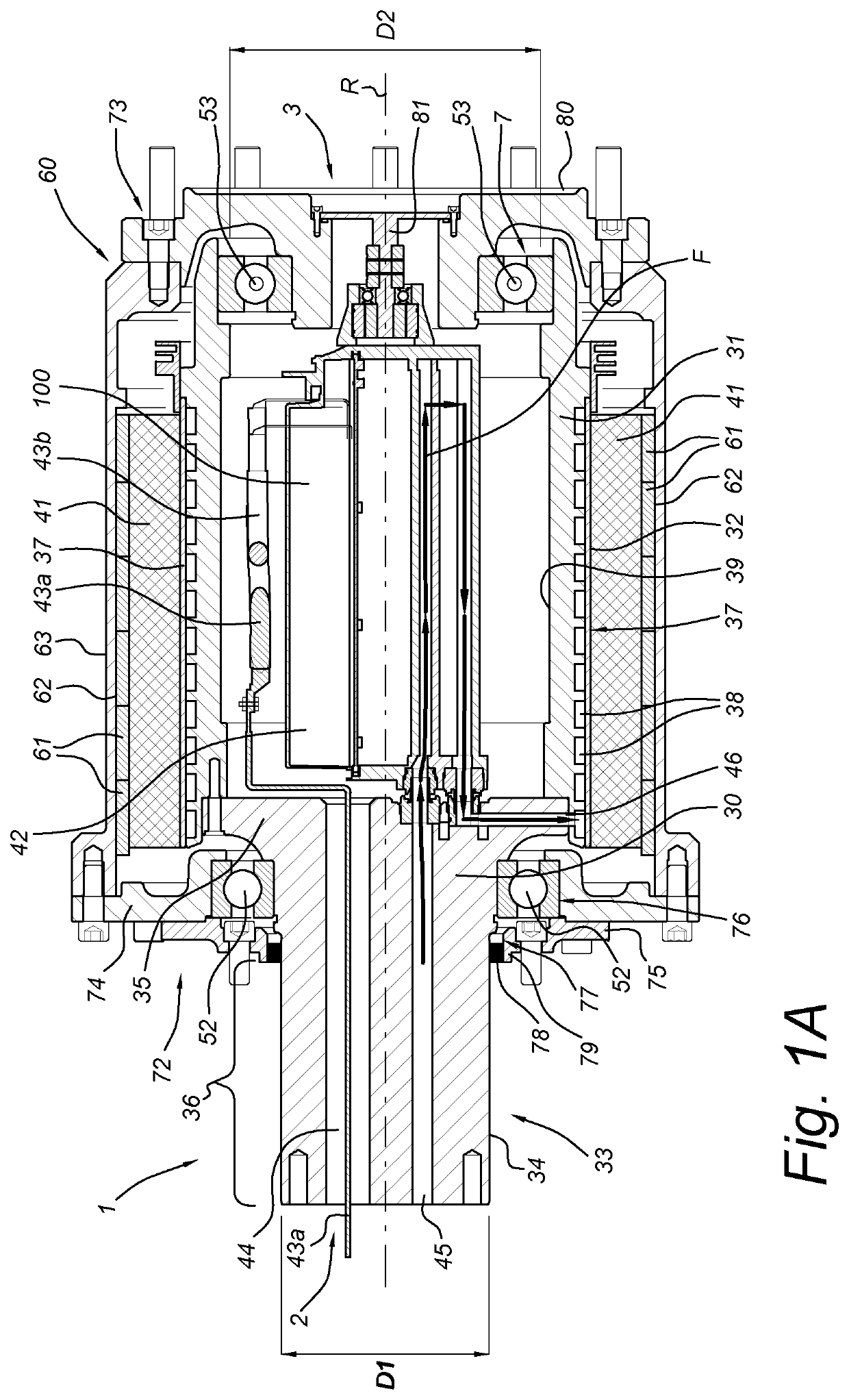
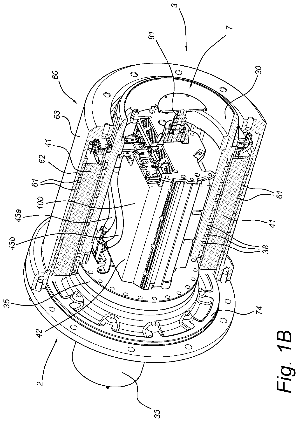
[0054]FIG. 1A shows a cross-sectional view of a drive assembly 1 for use with the present invention. The drive assembly comprises a stator 30 with a hollow stator body 31 which has an outer surface 32 around which a rotor 60 is arranged. The drive assembly further comprises an connector member 33, arranged at a vehicle side 2 of the assembly 1 for attaching the drive assembly to the vehicle. The connector member 33 comprises a shaft 34 with a diameter D1 and flange 35 which is fixedly connected to the stator body 31. The open end 7 of the hollow stator body 31 has an inner diameter D2 larger than D1, allowing control electronics 42 to be inserted through the open end 7 when the road side cover plate 80 and the road side bearings 53 are detached from the rotor 60. The flange 35 lies within the rotor 60 and has a larger diameter than a portion 36 of the shaft 34 which lies outside the peripheral surface 63 of the rotor 60. For supporting rotational movement of the rotor 60 around the ...


PUM


Abstract

An in-wheel motor for a vehicle includes: a stator with a connector attaching the stator to the vehicle, the connector including a shaft, an end plate of a larger diameter than the shaft, and a coolant passage through the end plate, the stator further including a hollow stator body with cylindrical outer surface and mounted to the connector. Cooling channels for circulating liquid coolant extend along the hollow stator body and are in fluid connection with the coolant supply duct, the cooling channels having an inlet for supply of liquid coolant to the plurality of channels and an outlet for discharging liquid coolant from the plurality of channels; wherein, at a side opposite from the connector member, the hollow stator body has an open end with a diameter larger than the diameter of the shaft. Also disclosed is a cooling jacket for such an in-wheel motor.

Description

FIELD OF THE INVENTION[0001]The present invention relates to an in-wheel motor comprising a stator provided with electromagnets and a plurality of cooling channels which extend along the stator body and through which coolant can flow for cooling the electromagnets. The invention further relates to a cooling jacket for use in an in-wheel motor.BACKGROUND ART[0002]US 201 3 / 01 261 43 A1 describes a cooling jacket for cooling an electric motor, wherein the cooling jacket has one or more continuous S-shaped pipes, covering the electric motor, for conducting working fluid, wherein each continuous S-shaped pipe at least has: a forwarding portion and a reversed portion, respectively extending along two circumferential directions which are parallel but opposite to each other; and a turning portion connected between the forwarding portion and the reversed portion. When the cooling jacket is used to cool the electric motor, the temperature of working fluid within the S-shaped pipes typically i...

Claims


Application Information

Patent Timeline
IPC IPC(8): H02K1/20H02K7/00H02K9/193H02K21/22B60K7/00
CPCH02K1/20H02K7/006H02K9/193H02K21/22B60K7/0007B60K11/02B60K2001/006H02K5/203Y02T10/64
Inventor VAN DER WAL, REINHARD PETER
Owner E TRACTION EURO BV
Why Eureka
Try Eureka