Low-Emissivity Glass

a technology of low emissivity and glass, applied in the direction of coatings, etc., can solve the problems of poor durability, poor mechanical durability, poor durability, etc., and achieve the effects of stable sputtering, excellent deposition rate, and excellent handling

Inactive Publication Date: 2020-06-18
KCC GLASS CORP
View PDF0 Cites 1 Cited by
  • Summary
  • Abstract
  • Description
  • Claims
  • Application Information

AI Technical Summary

Benefits of technology

[0009]Low-emissivity glass of the present invention is excellent in handling, long-term storage, and mechanical durability, and has an advantage in that the deposition rate is excellent and stable sputtering is possible compared to conventional low-emissivity glass using TiOxNy.

Problems solved by technology

In addition, low-emissivity glass is manufactured in the form of a glass substrate / dielectric / silver / dielectric / protective layer due to the properties of silver having low durability.
However, due to the physical deposition and the use of relatively unstable silver, a coating layer is weak, and thus durability is poor.
However, in a region with a rainy season of high temperatures and humidity, durability, especially moisture resistance, is not good.

Method used


Image

  • Low-Emissivity Glass
  • Low-Emissivity Glass

Examples


example 1

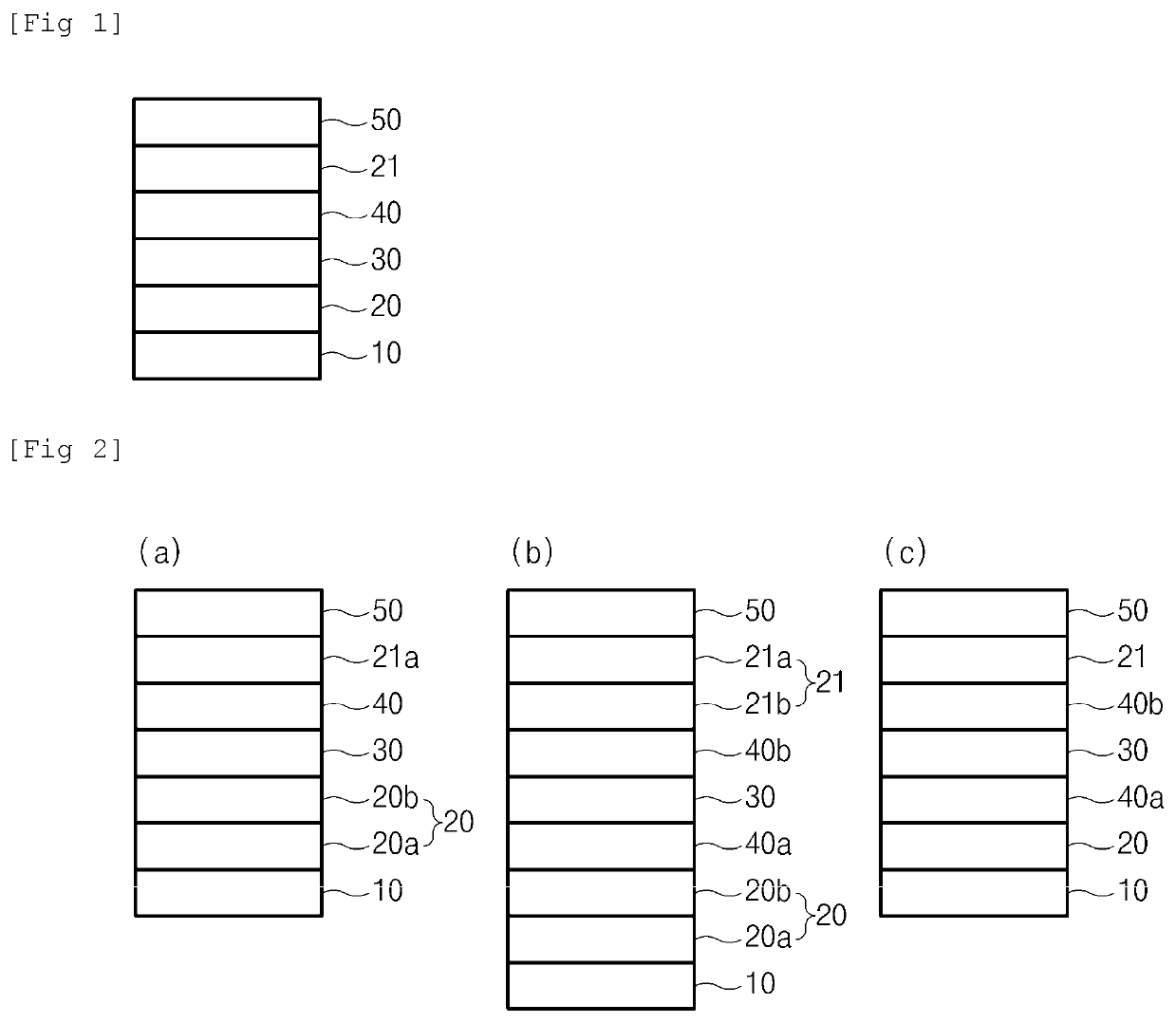
[0053]Using a Magnetron sputter coater, low-emissivity glass was manufactured having a multi-layered coated film which has the composition and thickness shown in Table 1 below formed on a 6 mm transparent glass substrate.

[0054]A first dielectric layer (SiAlNx, x=1.3-1.5) was coated under a nitrogen / argon (nitrogen ratio: 40 vol %) atmosphere, and an absorption layer (NiCr alloy) was coated under an argon 100% atmosphere, and a metal layer (Ag) was coated under an argon 100% atmosphere. Thereafter, the absorption layer (NiCr alloy) was coated on the metal layer (Ag) under an argon 100% atmosphere, a second dielectric layer (SiAlNx, x=1.3-1.5) was coated under a nitrogen / argon (nitrogen ratio: 40 vol %) atmosphere, and a ZRN layer was coated as a coating layer on a nitrogen / argon (nitrogen ratio: 40 vol %) atmosphere using a metal target to manufacture low-emissivity glass.

example 2

[0055]Low-emissivity glass was manufactured in the same manner as in Example 1 except that a ZrN layer was coated as a coating layer under a nitrogen 100% atmosphere using a metal target.

TABLE 1ExamplesFilm type (film thickness: nm)1Glass / SiAlNx (30 nm) / NiCr(0.3 nm) / Ag(10 nm) / NiCr(0.2nm) / SiAlNx(30 nm) / ZrN N2 40%, 5 nm)2Glass / SiAlNx(30 nm) / NiCr(0.3 nm) / Ag(10 nm) / NiCr(0.2 nm) / SiAlNx(30 nm) / ZrN(N2 100%, 5 nm)

experimental example

[0058]The physical properties of the low-emissivity glass which was obtained in each of Examples and Comparative Examples were measured according to the following method, the results are shown in Table 3 below.

[0059]Moisture Resistance

[0060]One specimen coated with the low-emissivity glass manufactured in each of Examples and Comparative Examples was prepared to a size of 100×100 mm, and then placed in a constant temperature and humidity room (relative humidity 80±10%, temperature 30±2° C.). After 24 hours of curing, the specimen was taken out at 1-day (24 hours) intervals and water was removed therefrom with a cloth to determine whether the specimen satisfies the size and number of a pinhole (ϕ) and the following 1) to 3).

[0061]1) 4.0 mm ϕ more than one not allowed

[0062]1) 2.0 mm ϕ more than three not allowed

[0063]3) Front small pinhole not allowed

[0064]Scratch Resistance

[0065]1) General

[0066]One specimen coated with the low-emissivity glass manufactured in each of Examples and Com...


PUM

PropertyMeasurementUnit
thicknessaaaaaaaaaa
thicknessaaaaaaaaaa
thicknessaaaaaaaaaa

Abstract

The present invention relates to low-emissivity glass comprising: a glass substrate; a first dielectric layer formed on the glass substrate; a metal layer formed on the first dielectric layer; an absorbent layer formed on the metal layer; a second dielectric layer formed on the absorbent layer; and a coating layer formed on the second dielectric layer and containing Zr, whereby a low-emissivity glass having good and excellent handling and long-term storage properties is provided.

Description

CROSS-REFERENCE TO RELATED APPLICATIONS[0001]This application claims the benefit of Korean Patent Application No. 10-2017-0093847, filed on 25 Jul. 2017, in the Korean Intellectual Property Office, the disclosure of which is incorporated herein in its entirety by reference.TECHNICAL FIELD[0002]The present invention relates to low-emissivity glass having excellent durability, handling and long-term storage properties.BACKGROUND ART[0003]By being specially coated on a glass surface, low-emissivity glass reflects solar radiant heat in the summer and preserves infrared rays generated from an indoor heater in the winter, thereby increasing the energy-saving effect of a building.[0004]Such low-emissivity glass is manufactured largely in two ways. One is a method in which a semiconductor precursor uniformly applied on a hot glass ribbon during a glass manufacturing process such that the precursor is decomposed and coated by glass heat. The other is a method in which coating is performed th...

Claims


Application Information

Patent Timeline
Patent Type & Authority Applications(United States)
IPC IPC(8): C03C17/36
CPCC03C17/366C03C17/3639C03C17/3626C03C2218/156C03C17/3644C03C17/3649C03C17/3618C03C17/36C03C17/3652C03C17/3681C03C2217/78
Inventor PARK, JOON YOUNGKANG, HYUN MINKIM, JIN YONGOH, YOUNG HOONYOON, SUNG KUNYU, BO NALEE, HYOUN JOOLEE, JE HYANGKIM, MIN JU
Owner KCC GLASS CORP
Why Eureka
Try Eureka