
Methods and system for determining engine air-fuel ratio imbalance

Active Publication Date: 2020-06-18
FORD GLOBAL TECH LLC
View PDF20 Cites 2 Cited by
  • Summary
  • Abstract
  • Description
  • Claims
  • Application Information

AI Technical Summary

Benefits of technology

This patent describes a method for controlling the air-fuel ratio in internal combustion engines to reduce emissions and improve engine performance. By using a single oxygen sensor in the exhaust system, the method can determine air-fuel imbalances in individual cylinders and adjust the fuel injection accordingly to achieve a uniform air-fuel ratio for all cylinders. This approach improves engine performance and reduces emissions without adding any significant cost to the system.

Problems solved by technology

Manufacturing variation, wear, and dimensional differences of intake passages for the engine's cylinders may lead to air-fuel imbalances in the cylinders.
The air-fuel imbalances within the cylinders may cause variation of exhaust gases that exit the engine cylinders and enter a catalyst in the engine's exhaust system.
The variation of exhaust gases entering the catalyst may reduce catalyst efficiency and increase exhaust emissions.
However, it may be difficult to determine individual cylinder air-fuel ratio imbalances for an engine that includes a plurality of cylinders and only one pre-catalyst oxygen sensor for a bank of cylinders because the single oxygen sensor may be exposed to exhaust gases from all cylinders of a cylinder bank.

Method used


Image

  • Methods and system for determining engine air-fuel ratio imbalance
  • Methods and system for determining engine air-fuel ratio imbalance
  • Methods and system for determining engine air-fuel ratio imbalance

Examples


Embodiment Construction

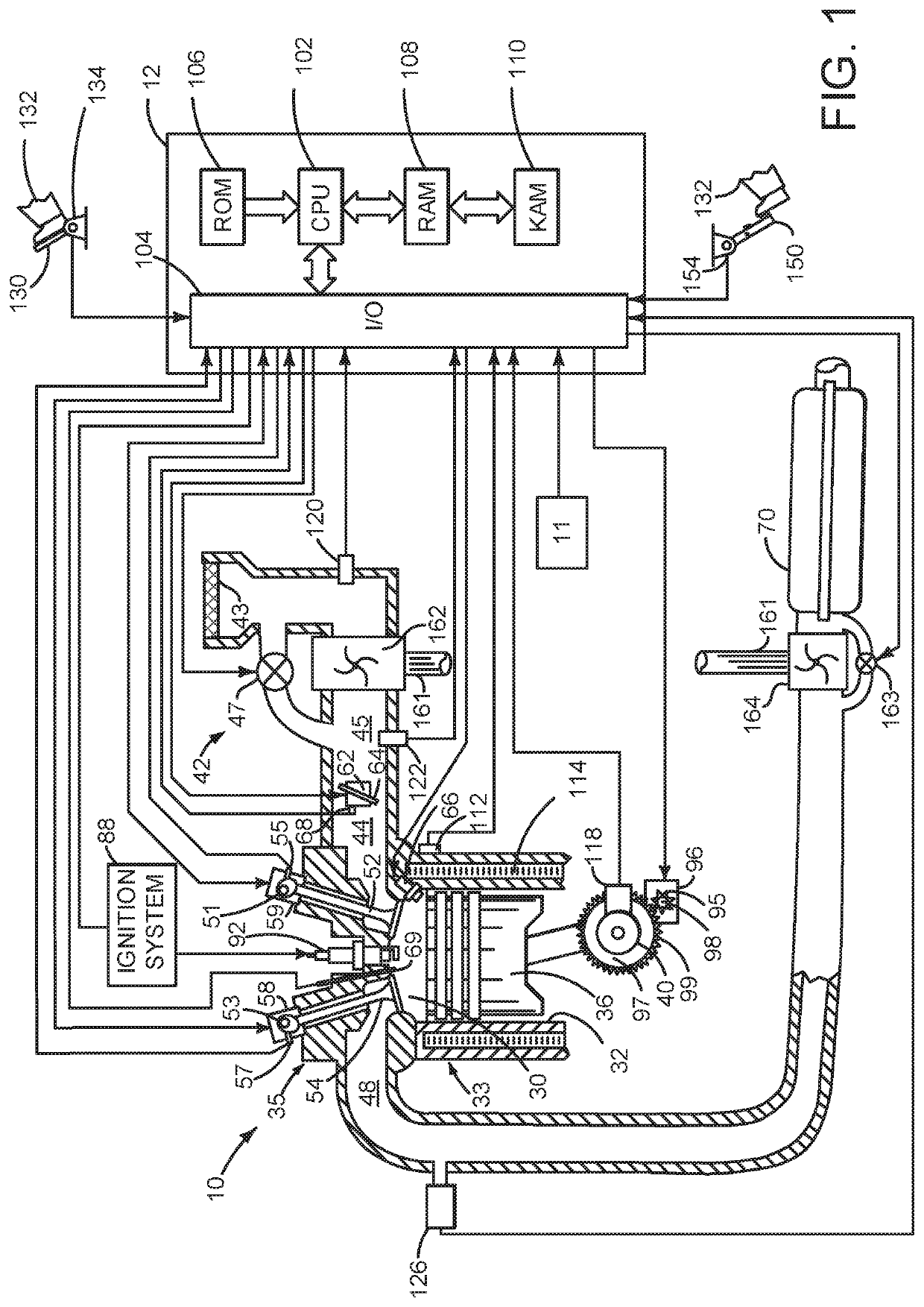
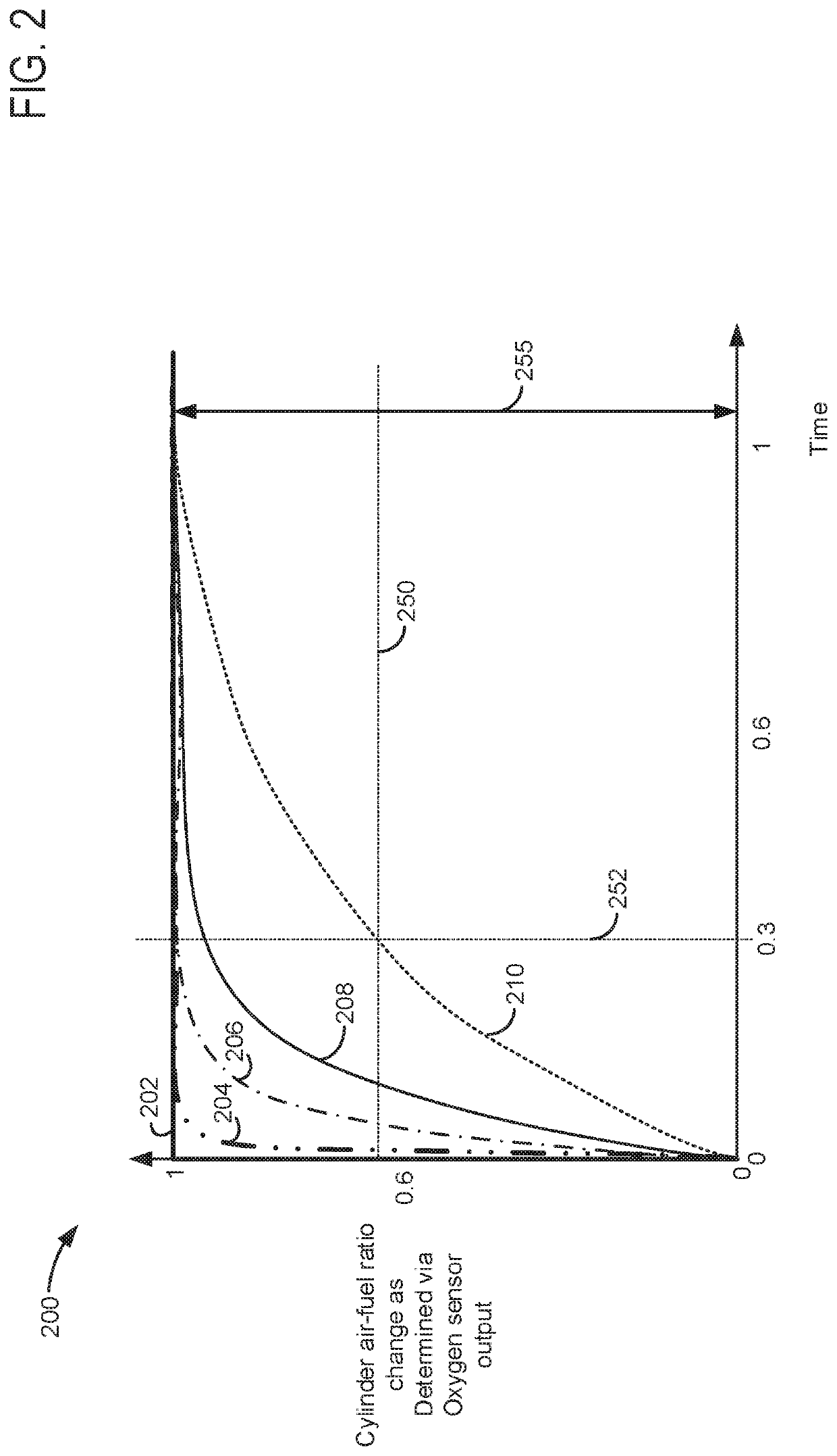
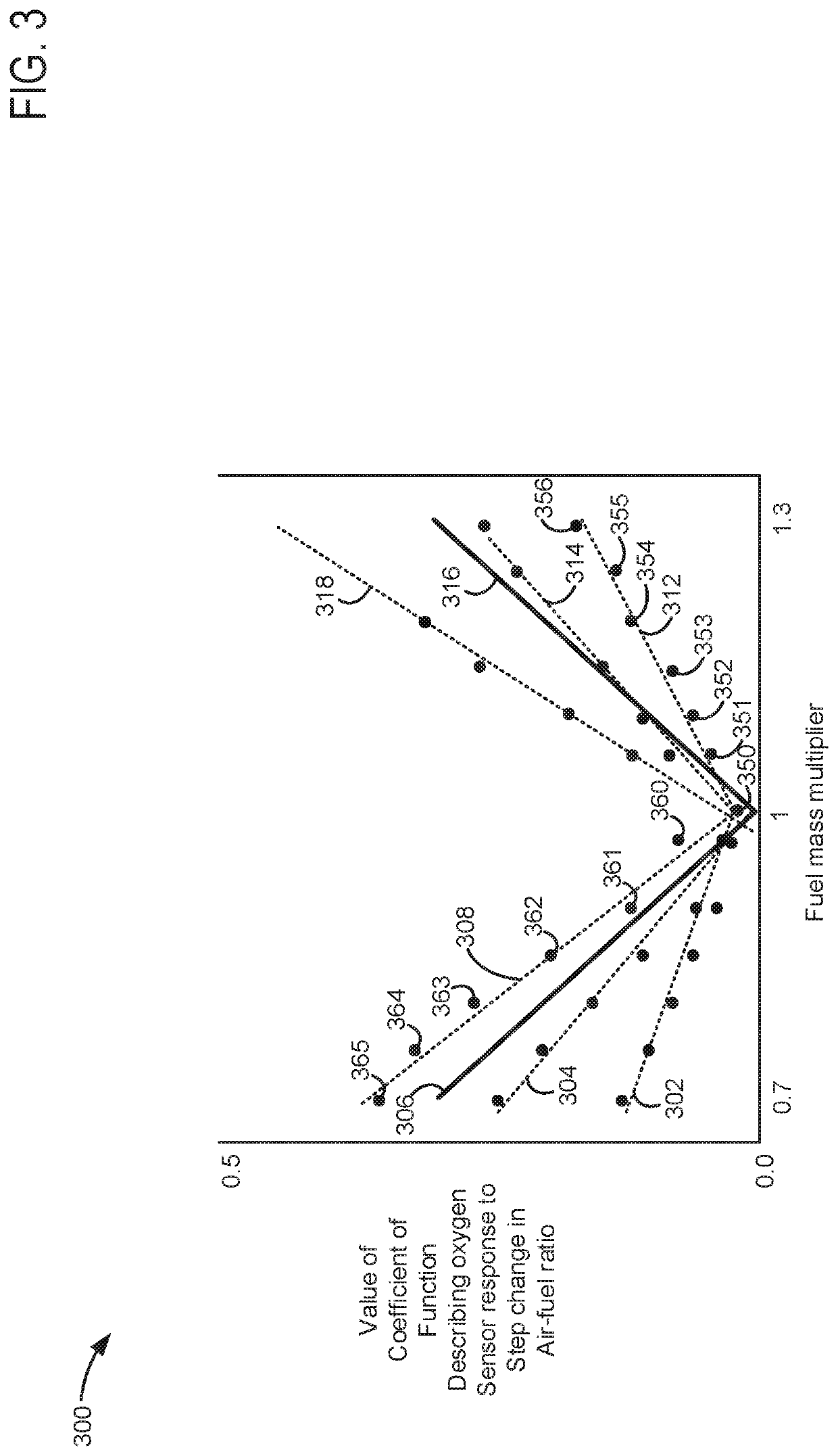
[0014]The present description is related to operating an internal combustion engine of a vehicle. The engine may be of the type shown in FIG. 1. The engine may operate with a lambda or air-fuel ratio imbalance between one or more cylinders that may lead to increased engine emissions. The imbalance may be detected via inputting step changes in air-fuel ratio to the engine cylinders as shown in FIG. 2. Oxygen sensor output responsive to the step input in air-fuel ratio or lambda may be applied to generate straight lines showing a relationship between a coefficient of a function and an air-fuel ratio multiplier as shown in FIG. 3. One or more lines may be the basis for determining cylinder air fuel imbalance as depicted in FIG. 4. A method for determining air-fuel ratio imbalance in engine cylinders and compensating for the same is shown in the method of FIGS. 5 and 6.

[0015]Referring to FIG. 1, internal combustion engine 10, comprising one or more cylinders, one cylinder of which is sh...


PUM


Abstract

Systems and methods for operating an engine that includes an oxygen sensor and one or more fuel injectors for each engine cylinder are described. In one example, lines describing a relationship between a fuel mass multiplier and a coefficient of a function describing output of an oxygen sensor to a step change in fuel mass are a basis for determining air-fuel imbalance of engine cylinders.

Description

FIELD[0001]The present description relates to methods and a system for determining and compensating for engine cylinder air-fuel ratio imbalance.BACKGROUND AND SUMMARY[0002]An internal combustion engine may include a plurality of cylinders in which combustion occurs. Each of the plurality of cylinders may receive fuel from a dedicated fuel injector. Further, each of the plurality of cylinders may receive air from a dedicated air intake passage. Manufacturing variation, wear, and dimensional differences of intake passages for the engine's cylinders may lead to air-fuel imbalances in the cylinders. The air-fuel imbalances within the cylinders may cause variation of exhaust gases that exit the engine cylinders and enter a catalyst in the engine's exhaust system. The variation of exhaust gases entering the catalyst may reduce catalyst efficiency and increase exhaust emissions. However, it may be difficult to determine individual cylinder air-fuel ratio imbalances for an engine that incl...

Claims


Application Information

Patent Timeline
IPC IPC(8): F02D41/14
CPCF02D2200/0614F02D41/1454F02D41/1475F01N2560/025F02D41/1441F02D37/02F02D41/0085F02D41/30F02P5/1512F02D41/0002F02D41/1401F02D41/2422F02D41/2454F02D2041/1433F02D2200/0404F02D2200/602Y02T10/40
Inventor KLUZNER, MICHAELJENTZ, ROBERTBEHR, KENNETH JOHNWEBER, CHRISTOPHERBAGNASCO, ANDREW
Owner FORD GLOBAL TECH LLC
Learn More