

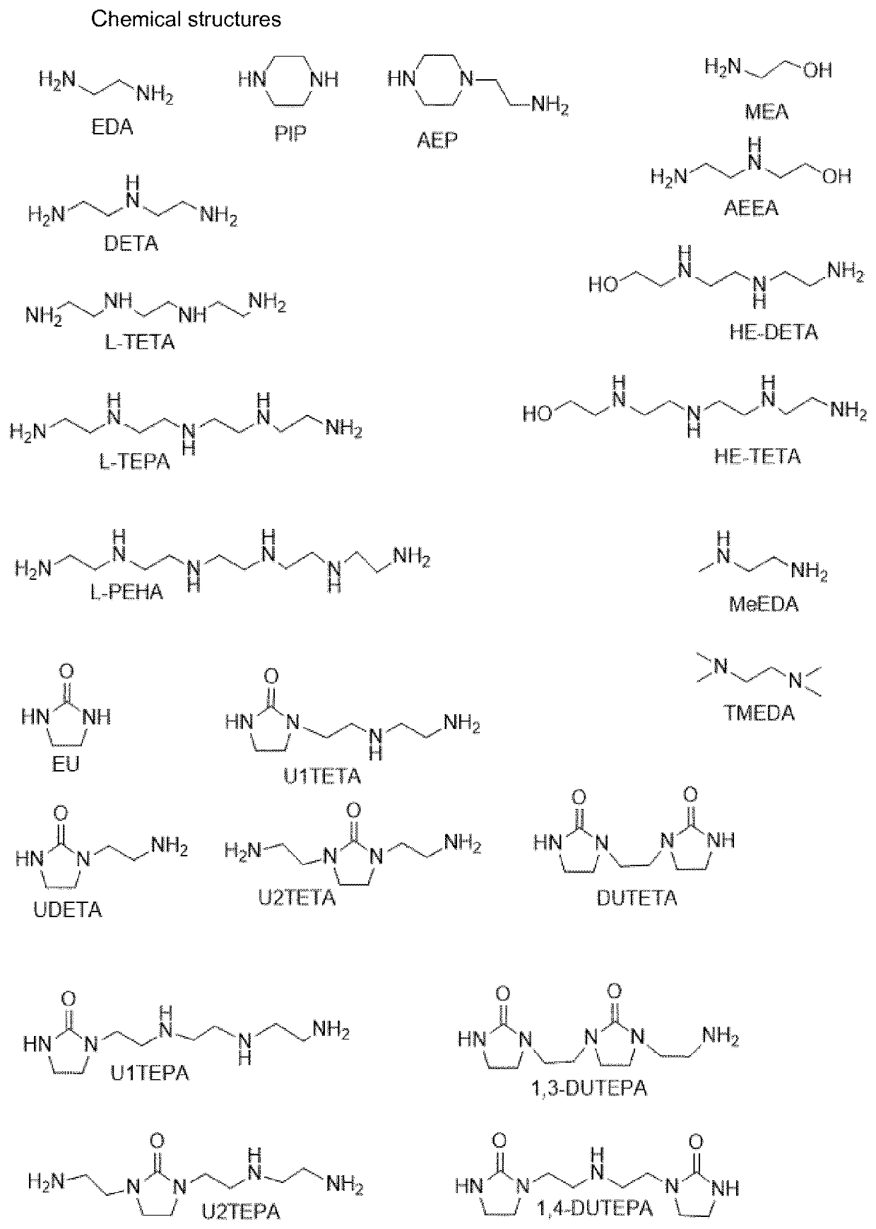
Process for converting cyclic alkyleneureas into their corresponding alkyleneamines
- Summary
- Abstract
- Description
- Claims
- Application Information
AI Technical Summary
Benefits of technology
Problems solved by technology
Method used
Image


Examples
example 1
n of DUTETA at a Water to Urea Ratio of 4:1
[0052]The experimental set-up used in the experiment described below was a pressure vessel with a volume of 2000 ml equipped with a condenser, a pressure regulator, a gas distributor and a mixer. The pressure in the reaction vessel and the condenser was kept constant at 30 bara using the pressure regulator. The top temperature of the condenser was kept between 30 and 60° C. During the reaction the mixture was continuously stirred and a constant flow of N2 gas was supplied to the reactor vessel using the gas distributor. Gasses or vapors that were produced or fed to the system during the reaction in excess of 30 bara were allowed to escape the reactor via the condenser and the pressure regulator.
[0053]A reaction mixture was prepared by mixing 430 grams of DUTETA and 300 grams of H2O. The molar ratio of H2O to urea moieties was 4:1. The mixture was kept at 270° C. for 5.4 hours in the reactor described above. The N2 gas flow used was ˜2 L / min...
examples 2-4
f DUTETA at Different Water to Urea Ratios
[0055]Example 1 was repeated at different water to urea ratios in the same experimental set-up. The reaction time was selected such in each experiment that the removal rate could be calculated with reasonable accuracy. The results are presented in table 1.
TABLE 1ExampleExampleExampleExample4123CompH2O / U (mol / mol)410150Pressure (bar)35343434Temperature (C.)270270270270Reaction time (hr)5.36.719.26.6N2 flow (L / min)2222ResultsRemoval rate0.540.390.220.11(mol / kg / hr)U-removal70%73%49%73%L-TETA yield54%51%21%25%Selectivity (L-TETA77%71%44%34%yield / U-removal)
[0056]In Table 1, Examples 1, 2, and 3 are according to the invention. They show that operation at water to urea moiety molar ratios of 4:1, 10:1, and 1:1 result in a substantial removal of urea groups with a good selectivity to L-TETA. Contrary to expectations, the presence of more water in Comparative Example 4 (H2O / U molar ratio is 50:1) leads to a lower selectivity for L-TETA, and also to a...
example 5
n of UDETA at a Water to Urea Ratio of 4:1
[0057]In the experimental set-up as described in Example 1, a reaction mixture was prepared by mixing 350 grams of UDETA and 191 grams of H2O. The molar ratio of H2O to urea moieties was 4:1. The mixture was kept at 270° C. for 5.8 hours in the reactor described above. The N2 gas flow used was ˜4 L / min. Analysis by gas chromatography using a flame ionization detector (GC-FID analysis) showed that the conversion of UDETA into DETA was 55% and that 60% of the initial urea-groups were removed from the system. The average removal rate was 0.62 mol / kg / hr.
PUM
| Property | Measurement | Unit |
|---|---|---|
| Temperature | aaaaa | aaaaa |
| Temperature | aaaaa | aaaaa |
| Temperature | aaaaa | aaaaa |
Abstract
Description
Claims
Application Information