Noise cancellation circuit and operating method thereof

a technology of noise cancellation circuit and operating method, which is applied in the field of noise cancellation circuit, can solve the problems of increasing the power consumption of the analog front-end, increasing the required circuit area, and reducing the input signal-to-noise ratio, so as to effectively reduce external environmental noise, prevent the increase of system processing complexity, and eliminate noise

Inactive Publication Date: 2020-07-09
RAYDIUM SEMICON
View PDF0 Cites 5 Cited by
  • Summary
  • Abstract
  • Description
  • Claims
  • Application Information

AI Technical Summary

Benefits of technology

[0013]In an embodiment, the noise cancellation circuit is applied to cancel noise of capacitive touch sensing to increase accuracy of capacitive touch sensing.
[0016]Compared to the prior art, the noise cancellation circuit of the invention uses a differential structure to eliminate noise and uses a signal modulation mechanism to modulate back to a single-ended channel change, which can not only effectively reduce external environmental noise, but also prevent the system processing complexity from increasing. Therefore, the disadvantages of the prior art can be greatly improved, and the noise cancellation circuit of the invention can be applied to noise cancellation of capacitive touch sensing to effectively improve the accuracy of capacitive touch sensing.

Problems solved by technology

However, there are many disadvantages to the above-mentioned three conventional solutions, in which the disadvantages of the amplified feedback capacitor mechanism include increasing the power consumption of the analog front-end, increasing the required circuit area, decreasing the input signal-to-noise ratio and increasing detection difficulty, etc.
; the disadvantages of the current mirror mechanism include decreasing the input signal-to-noise ratio and increasing detection difficulty; the disadvantages of the differential mechanism include the obtained output voltage change is the difference between channels which will cause the complexity of the back-end digital signal processing and require additional processing of boundary conditions.

Method used


Image

  • Noise cancellation circuit and operating method thereof
  • Noise cancellation circuit and operating method thereof
  • Noise cancellation circuit and operating method thereof

Examples


Embodiment Construction

[0027]An embodiment of the invention is a noise cancellation circuit. In this embodiment, the noise cancellation circuit can be applied to capacitive touch sensing, such as noise cancellation for self-capacitive touch sensing, to improve the accuracy of touch sensing, but not limited to this.

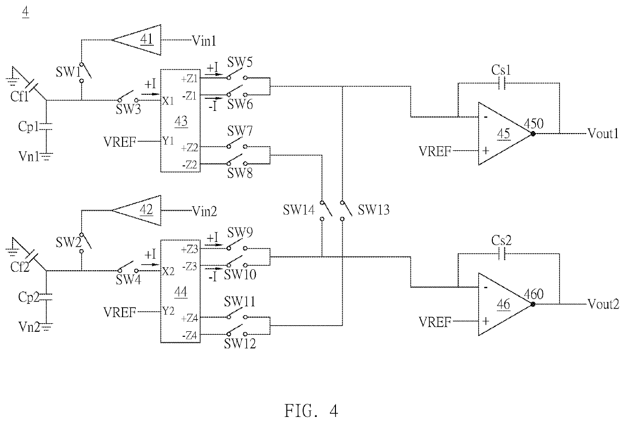
[0028]Please refer to FIG. 4. FIG. 4 is a schematic diagram of the noise cancellation circuit in this embodiment. As shown in FIG. 4, the noise cancellation circuit 4 includes a first switch SW1 to a fourteenth switch SW14, a first analog buffer 41, a second analog buffer 42, a first current conveyor 43, a second current conveyor 44, a first operational amplifier 45, a second operational amplifier 46, a first feedback capacitor Cf1, a second feedback capacitor Cf2, a first parallel capacitor Cp1, a second parallel capacitor Cp2, a first series capacitor Cs1 and a second series capacitor Cs2.

[0029]The first analog buffer 41 receives a first input signal Vin1 and the second analog buffer 42 receiv...


PUM


Abstract

A noise cancellation circuit includes a first switch to a fourteenth switch, a first / second analog buffer, a first / second feedback capacitor, a first / second parallel capacitor, a first / second current conveyor, a first / second operation amplifier and a first / second series capacitor. In a first phase, the first switch and second switch are turned on and the remaining switches are not turned on. In a second phase, the third to fifth switches, the eighth to ninth switches and the twelfth to fourteenth switches are turned on and the remaining switches are not turned on. In a third phase, the first switch and the second switch are turned on and the remaining switches are not turned on. In a fourth phase, the third to fifth switches, the seventh switch, the tenth switch and the twelfth to fourteenth switches are turned on and the remaining switches are not turned on.

Description

BACKGROUND OF THE INVENTION1. Field of the Invention[0001]The invention relates to noise cancellation; in particular, to a noise cancellation circuit and an operating method thereof.2. Description of the Prior Art[0002]In a capacitor detection environment with large external noise, in order to avoid the situation that the external noise and signal changes cannot be fully reflected due to the oversaturation of the output terminal of the analog front end (AFE), the conventional solutions can be divided into the following three types:[0003](1) Amplified feedback capacitor mechanism: As shown in FIG. 1, since the output voltage Vout is inversely proportional to the feedback capacitor Cf, when the feedback capacitor Cf increases, the output voltage Vout will become smaller.[0004](2) Current mirror mechanism: As shown in FIG. 2, the original input current IN is reduced to IN / α through the current conveyor 22. Since the output voltage Vout is inversely proportional to the ratio α, when the...

Claims


Application Information

Patent Timeline
Patent Type & Authority Applications(United States)
IPC IPC(8): H03K17/96
CPCH03K2217/960735G01R27/2605H03K2217/96015H03K17/962G06F3/0418G06F3/044H03K2217/960705G06F3/04182
Inventor CHEN, CHIH-HSIUNG
Owner RAYDIUM SEMICON
Why Eureka
Try Eureka