Engine system

a compression ignition and control apparatus technology, applied in mechanical apparatus, electric control, machines/engines, etc., can solve the problems of less scattering of fuel spray, longer time required for fuel spray to reach the lip portion of the piston, etc., to achieve the effect of increasing the time required for fuel spray to reach the lip portion, increasing the fuel distribution to the lower cavity, and increasing the penetration of fuel spray

Active Publication Date: 2020-07-30
MAZDA MOTOR CORP
View PDF0 Cites 2 Cited by
  • Summary
  • Abstract
  • Description
  • Claims
  • Application Information

AI Technical Summary

Benefits of technology

[0027]When the injection amount of the main injection increases, the penetration of the fuel spray becomes higher. When the penetration of the fuel spray becomes higher, the time required for the fuel spray to reach the lip portion becomes shorter, and hence the fuel distributed to the lower cavity increases. When the injection amount of the main injection increases, the fuel can be combusted with use of a large amount of oxygen in the lower cavity. The air utilization rate of the engine is improved. Fuel efficiency of the automobile is improved and the exhaust gas becomes cleaner.
[0028]As described above, in the engine system, the distribution ratio between the fuel for the upper cavity and the fuel for the lower cavity does not change even when the speed of the engine changes.

Problems solved by technology

When the pressure in the combustion chamber is high, the fuel spray scatters less easily.
When the fuel spray scatters less easily, the time required for the fuel spray to reach the lip portion of the piston is longer.

Method used


Image

  • Engine system
  • Engine system
  • Engine system

Examples


Embodiment Construction

[0045]An embodiment of an engine system is described below with reference to the accompanying drawings. The engine system described below is an example.

Overall Configuration of Engine System

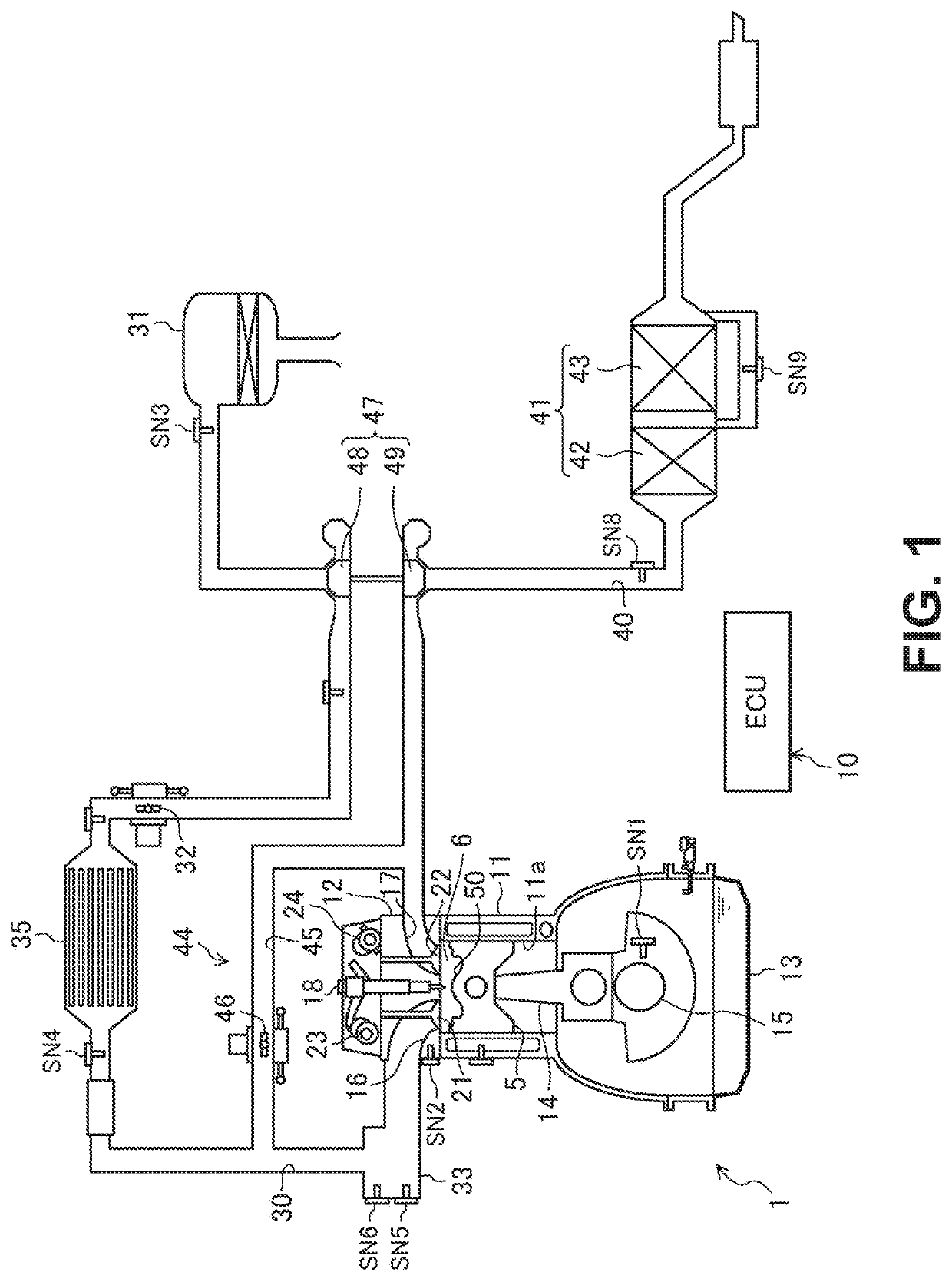
[0046]FIG. 1 exemplifies the overall configuration of an engine system. The engine system is installed in a four-wheeled automobile. The engine system includes an engine 1, an intake passage 30, an exhaust passage 40, an exhaust air purification apparatus 41, an EGR (exhaust gas recirculation) apparatus 44, and a turbocharger 47.

[0047]The engine 1 is a diesel engine to which fuel containing light oil as the main component thereof is supplied. The fuel is combusted by compression ignition. The automobile travels by the operation of the engine 1. The engine 1 includes a cylinder block 11, a cylinder head 12, and an oil pan 13. In the cylinder block 11, a plurality of cylinders 11a (only one is illustrated in FIG. 1) are provided. The cylinder head 12 is disposed on the cylinder block 11. The oil pa...


PUM


Abstract

In a compression-ignition engine having a two-stage cavity, the distribution ratio between fuel for an upper cavity and fuel for a lower cavity is maintained even when the operational state of the engine changes. A piston of the compression-ignition engine includes a lower cavity, an upper cavity, and a lip portion between the lower cavity and the upper cavity. A controller causes a main injection and at least one pilot injection to be executed when the engine operates in a first state and a second state in which the speed is higher than the speed in the first state. The fuel spray is distributed to the lower cavity and the upper cavity. The controller increases an injection amount per pilot injection when the engine operates in the second state than when the engine operates in the first state.

Description

BACKGROUND OF THE INVENTIONField of the Invention[0001]The technology disclosed herein relates to a control apparatus of a compression-ignition engine.Description of the Related Art[0002]Japanese Patent Laid-Open No. 2010-101243 discloses a diesel engine in which a first cavity, a second cavity, and a protruding portion are provided in a piston.[0003]Fuel spray jetted out from a fuel injection nozzle is distributed to the first cavity and the second cavity by the protruding portion. The air utilization rate of an engine having a so-called two-stage cavity can be increased, and hence the engine is advantageous in terms of improving fuel efficiency and producing cleaner exhaust gas.[0004]The applicant of the present application has realized rapid multi-stage combustion in which the change of the heat generation rate with respect to the progress of the crank angle forms a hill due to the heat generation of the pre-combustion and the heat generation of the main combustion being in smoot...

Claims


Application Information

Patent Timeline
Patent Type & Authority Applications(United States)
IPC IPC(8): F02D41/40F02M61/14F02F3/26F02D41/00F02B1/12F16J1/00
CPCF02B1/12F02D2200/0406F02D2041/389F02D2200/101F02D41/403F02F3/26F02M61/14F02D2200/0404F16J1/00F02D41/0007F02D2200/0602F02B23/0669F02B23/0693F02B23/0672F02B2023/103F02D41/405F02B23/0651Y02T10/12
Inventor SHIRAHASHI, NAOTOSHIUESUGI, YASUNORIMATSUBARA, TAKESHI
Owner MAZDA MOTOR CORP
Why Eureka
Try Eureka