Composite magnetic material, magnet comprising the material, motor using the magnet, and method of manufacturing the composite magnetic material

a composite magnetic material and magnet technology, applied in the direction of magnetic materials, magnetic circuits characterised by magnetic materials, magnetic bodies, etc., can solve the problems of rare metals of rare earth elements, uneven distribution of earth's magnetic properties, high cost, etc., and achieve the nano-composite magnet having sufficiently high magnetic properties. the goal of the patent literature 1 is to achieve the effect of nano-composite magnets, the optimization of the particle size of hard magnetic particles and the distance between hard magnetic particles

Inactive Publication Date: 2020-07-30
CANON KK
View PDF23 Cites 3 Cited by
  • Summary
  • Abstract
  • Description
  • Claims
  • Application Information

AI Technical Summary

Benefits of technology

[0009]A composite magnetic material as one aspect of the present invention includes: a soft magnetic phase including a magnetic material containing a ferromagnetic material including Fe or Co as a main component; and a plurality of hard magnetic particles present and dispersed in a form of islands in the soft magnetic phase, in which the hard magnetic particles have an average particle size of 2 nm or more and include a magnetic material containing a ferrimagnetic material or an antiferromagnetic material as a main component, and an average distance between adjacent two of the hard magnetic particles is 100 nm or less.

Problems solved by technology

However, since rare-earth elements are rare metals and unevenly distributed on the earth and expensive, there has been an attempt to fabricate high-performance magnets using smaller amounts of rare-earth elements.
In other words, it is hard to say that Patent Literature 1 has achieved a nanocomposite magnet having sufficiently high magnetic properties.
In addition, in Patent Literature 1, optimization of the particle sizes of the hard magnetic particles and distances between the hard magnetic particles is insufficient in the state of the nanocomposite magnet obtained by densifying the above-describe d magnetic particles.
As described above, in the conventional nanocomposite magnet, the current situation is that the residual magnetic flux density and the coercive force decrease due to blockage of the exchange coupling and variation in the magnetic anisotropy, and sufficient magnet performances have not been achieved.

Method used


Image

  • Composite magnetic material, magnet comprising the material, motor using the magnet, and method of manufacturing the composite magnetic material
  • Composite magnetic material, magnet comprising the material, motor using the magnet, and method of manufacturing the composite magnetic material
  • Composite magnetic material, magnet comprising the material, motor using the magnet, and method of manufacturing the composite magnetic material

Examples


first embodiment

[0038](Structure of Composite Magnetic Material)

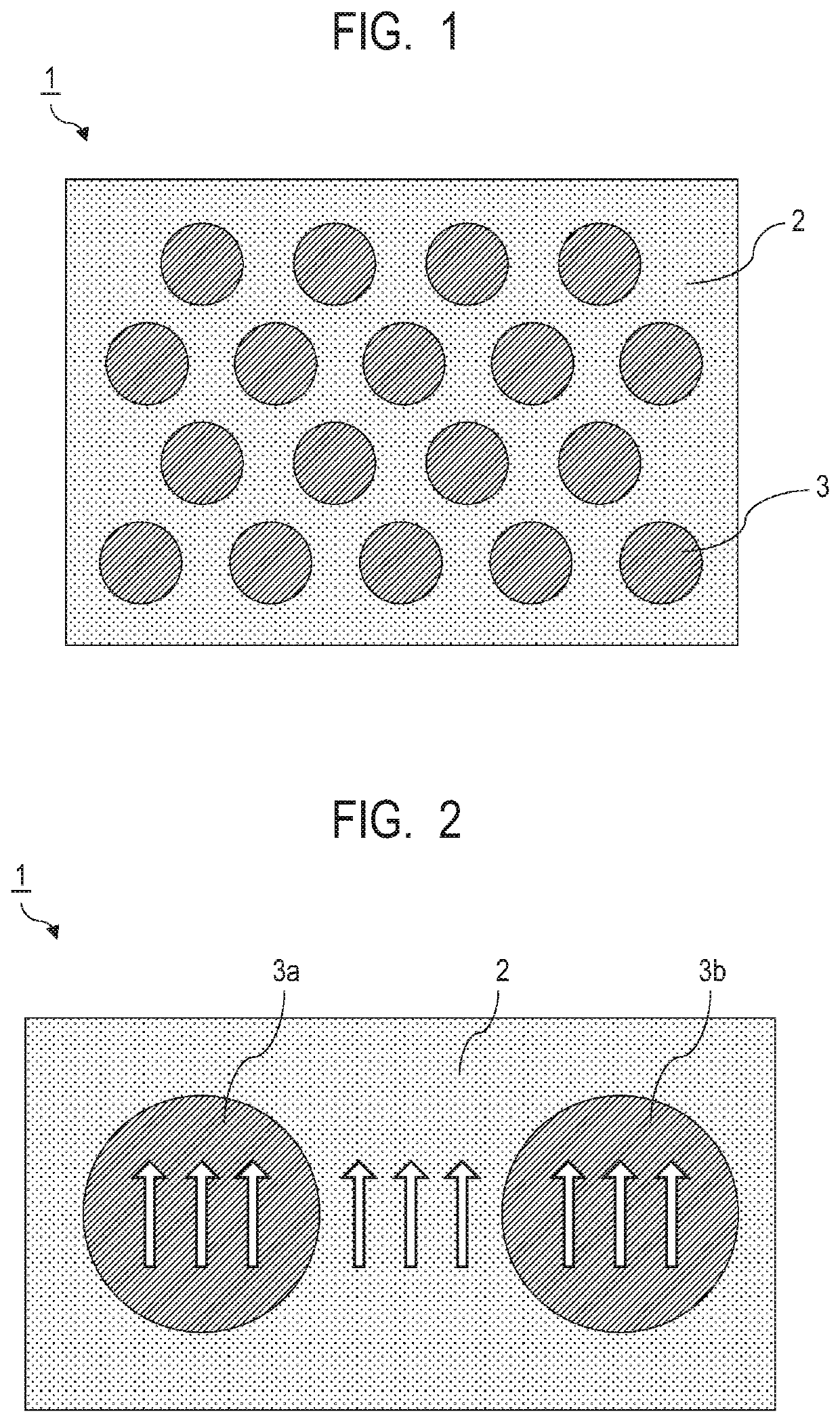
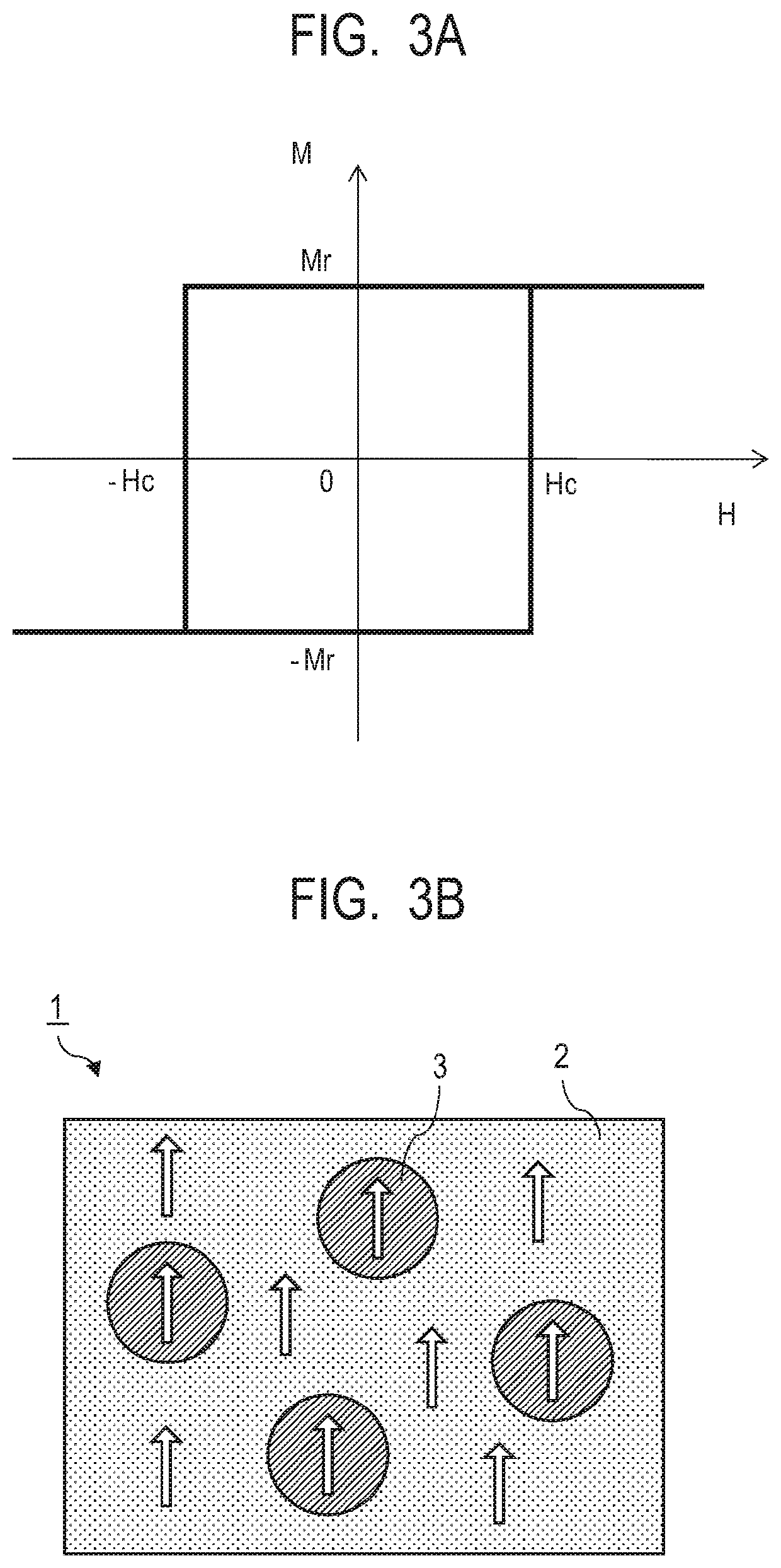
[0039]A composite magnetic material according to the present embodiment has a fine mixed structure in which two phases, that is, a phase of a soft magnetic material (soft magnetic phase) and a phase of a hard magnetic material (hard magnetic particles) are present adjacent to each other on the nm (nanometer) order. Having such a fine mixed structure makes it possible to cause an exchange coupling action to act between the soft magnetic phase and the hard magnetic particles. The exchange coupling action acting between the soft magnetic phase and the hard magnetic particles allows the magnetization switching of the soft magnetic phase to be suppressed by the magnetization of the exchange coupled hard magnetic particles when a magnetic switching field is applied. At this time, the magnetization curve behaves as if the soft magnetic phase and the hard magnetic particles are integrally a single-phase magnet due to the exchange coupling acti...

second embodiment

[0106]FIGS. 11A to 11C are diagrams illustrating time t responses of the revolutions per minute RPM of the motor. This is a driving sequence that controls the voltage⋅current of the coil of the motor so as to achieve a response as illustrated in FIG. 11A. Such a driving sequence is set in a sequencer that drives such a motor. The configuration including such a sequencer and such a motor is referred to as a motor unit. The revolutions per minute start increasing along with the start of drive, reaches specified revolutions per minute Rp after rise time (activation time) t1. The state of the revolutions per minute Rp is maintained for time t2. The revolutions per minute decreases to zero and the motor stops after fall time t3. During the time until the motor stops from the start of rotation (t1+t2+t3) or the time until the motor reaches and maintains a constant revolutions per minute (t1+t2), it is desirable that a ratio of the duration of the rise time t1 or the fall time t3, or the t...

third embodiment

[0111]The magnet of the present invention is effective in that the weight of the motor itself can be reduced, even when the magnet is provided in a fixed part (stator part) besides a moving part (rotor part) of the motor.

[0112]FIG. 13 is a graph illustrating a ratio of the weight of the magnet in a motor and a reduction rate of the weight of the motor itself. Three lines in FIG. 13 indicate cases where the ratios Rρ(%) of the specific gravities of a neodymium magnet, which is Comparative Example, and the magnet of the present invention were calculated as reduction rates in weight using Formula (6) and values Rρ of Formula 6 were 10%, 12%, 14%, respectively:

Rρ=(1−the specific gravity of magnet of the present invention / the specific gravity of the neodymium magnet)×100  Formula (6)

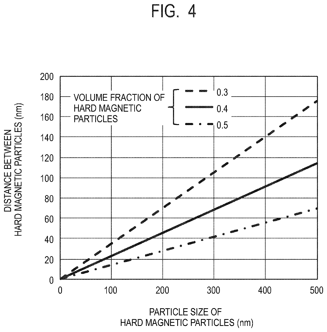
[0113]These are obtained by fabricating composite magnetic materials with the volume fractions of the hard magnetic particles set to 0.45, 0.40, 0.35, respectively, as illustrated in FIG. 6C, and setting the ...


PUM

PropertyMeasurementUnit
particle sizeaaaaaaaaaa
average distanceaaaaaaaaaa
volume fractionaaaaaaaaaa

Abstract

A composite magnetic material includes a soft magnetic phase including a magnetic material containing a ferromagnetic material including Fe or Co as a main component and a plurality of hard magnetic particles present and dispersed in a form of islands in the soft magnetic phase. The hard magnetic particles have an average particle size of 2 nm or more and include a magnetic material containing a ferrimagnetic material or an antiferromagnetic material as a main component while they are present with an average inter-particle distance of 100 nm or less in the soft magnetic phase. The composite magnetic material has excellent magnetic properties and can be made into a lightweight magnet to be used e.g. in a motor of an aircraft.

Description

CROSS-REFERENCE TO RELATED APPLICATIONS[0001]This application is a Continuation of International Patent Application No. PCT / JP2018 / 038922, filed Oct. 19, 2018, which claims the benefit of Japanese Patent Application No. 2017-203059, filed Oct. 20, 2017, Japanese Patent Application No. 2018-196167, filed Oct. 17, 2018, and Japanese Patent Application No. 2018-196169, filed Oct. 17, 2018, all of which are hereby incorporated by reference herein in their entirety.BACKGROUND OF THE INVENTIONField of the Invention[0002]The present invention relates to a composite magnetic material, a magnet containing the material, a motor using the magnet, and a method of manufacturing the composite magnetic material.Description of the Related Art[0003]Magnets using rare-earth elements such as neodymium have conventionally been widely used because such Magnets have high residual magnetic flux density and high coercive force and thus excellent magnetic properties. However, since rare-earth elements are r...

Claims


Application Information

Patent Timeline
Patent Type & Authority Applications(United States)
IPC IPC(8): H01F1/03H02K1/02H02K11/33C01G49/06C22C1/10
CPCC01P2004/64C01P2006/42H02K11/33H02K1/02C01G49/06H01F1/0302C22C2202/02C22C1/1026C22C32/0026C22C33/02B22F2998/10C01G49/02C01G49/08H01F1/0063H01F1/083B22F3/105
Inventor SASAGURI, DAISUKENISHIMURA, NAOKIOOTSUKA, MASANOBU
Owner CANON KK
Why Eureka
Try Eureka