Electric Power Distribution System

Active Publication Date: 2020-08-20
YAZAKI CORP
View PDF0 Cites 5 Cited by
  • Summary
  • Abstract
  • Description
  • Claims
  • Application Information

AI Technical Summary

Benefits of technology

[0011]According to one aspect of the present disclo

Problems solved by technology

However, since there is a difference between the output voltage of the DC/DC converter and

Method used


Image

  • Electric Power Distribution System
  • Electric Power Distribution System
  • Electric Power Distribution System

Examples


Embodiment Construction

[0018]Hereinafter, an embodiment of the present disclosure will be described with reference to the drawings, but the present disclosure is not limited to the following embodiment.

(Circuit Configuration)

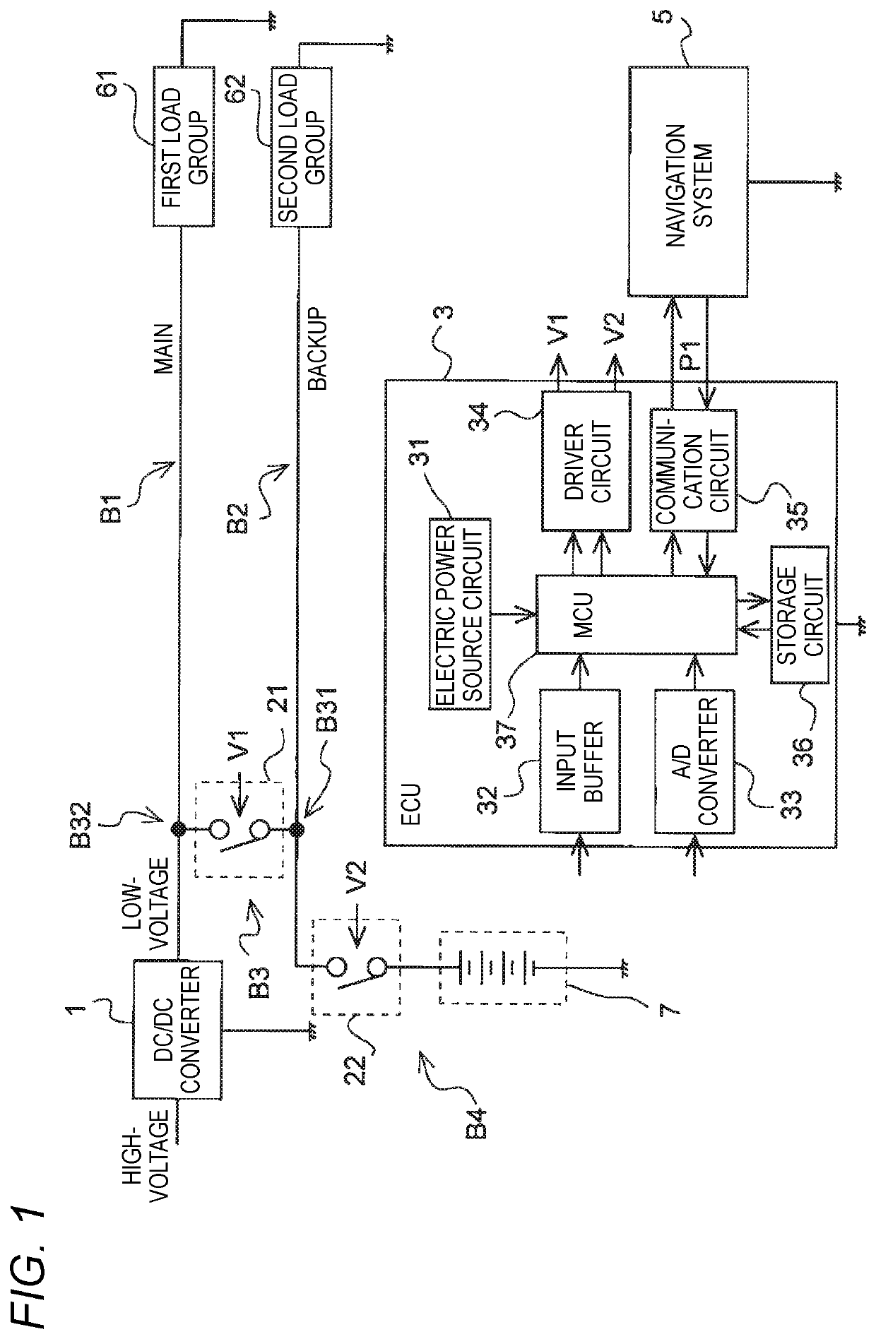
[0019]FIG. 1 is a block circuit diagram of an electric power distribution system according to an embodiment to which the present disclosure is applied. The electric power distribution system shown in FIG. 1 is mounted on a vehicle (not shown) and supplies electric power from at least one of a DC / DC converter 1 and a battery 7. The vehicle (not shown) is, for example, an electric vehicle, a plug-in hybrid vehicle (PHEV), a hybrid electric vehicle (HEV) or the like.

[0020]Electric power supply destinations are a first load group 61 and a second load group 62. The first load group 61 includes, for example, a typical load assumed in the related art and a load associated with automatic driving. The second load group 62 is a load minimally required for the automatic driving. The typical load...


PUM


Abstract

An electric power distribution system includes a first path through which electric power is supplied from a DC/DC converter to a driven load to be driven in a load group; a second path connected in parallel with the first path and through which electric power is supplied from the battery to the driven load; a third path connected in series with the second path and connecting the DC/DC converter and the battery; a first switching circuit provided in the third path and switched to either ON state or OFF state; and a control unit switching the first switching circuit to either the ON state or the OFF state based on travel route information of a navigation system. The control unit switches the first switching circuit to the ON state according to a peak current of a load current of the driven load derived from the travel route information.

Description

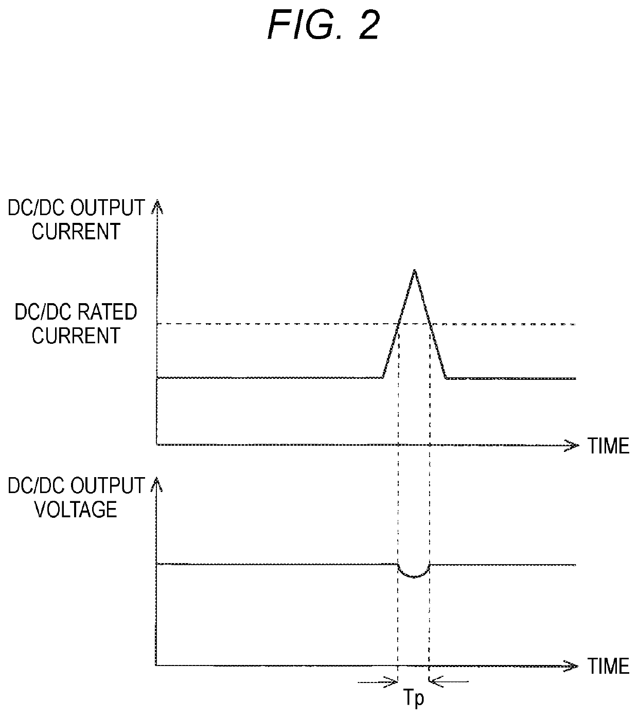
CROSS-REFERENCE TO RELATED APPLICATIONS[0001]This application is based on and claims priority under 35 USC 119 from Japanese Patent Application No. 2019-026304 filed on Feb. 18, 2019, the contents of which are incorporated herein by reference.TECHNICAL FIELD[0002]The present disclosure relates to an electric power distribution system.BACKGROUND ART[0003]In the related art, an electric power distribution system that supplies electric power from at least one of a DC / DC converter and a battery is mounted on a vehicle such as a hybrid vehicle or an electric vehicle (EV). The electric power distribution system includes a first path and a second pathCITATION LISTPatent Literature[0004]Patent Literature 1: JP-A-2017-221086SUMMARY OF INVENTION[0005]In general, when an output current of the DC / DC converter exceeds a rated current of the DC / DC converter, output efficiency decreases due to magnetic saturation of a coil included in the DC / DC converter, and an output voltage of the DC / DC convert...

Claims


Application Information

Patent Timeline
IPC IPC(8): B60L58/10H02J7/00B60L50/64B60L53/22
CPCB60L58/10B60L2210/10B60L53/22H02J7/0063B60L50/64H02J7/34H02J9/061H02J1/10H02J7/345H02J1/084H02J1/106H02J1/109Y02T10/70Y02T10/7072Y02T10/92Y02T90/14
Inventor SASAHARA, MASATO
Owner YAZAKI CORP
Why Eureka
Try Eureka