Process and apparatus for manufacturing a cutting tool by pressing

a pressing and manufacturing technology, applied in the field of pressing, can solve the problems of reducing the production efficiency of cutting tools, so as to reduce the time of grinding the flute, reduce the cost and energy expenditure of manufacturing process, and reduce the loss of material

Inactive Publication Date: 2020-08-27
LAMINA TECH
View PDF0 Cites 0 Cited by
  • Summary
  • Abstract
  • Description
  • Claims
  • Application Information

AI Technical Summary

Benefits of technology

[0008]It is an objective of the present invention to reduce the time, cost and energy expenditure of the manufacturing process by reducing the time of grinding the flutes and loss of material due to grinding.

Problems solved by technology

The above way of producing in particular round cutting tools suffers from several disadvantages and limitations.
The step of grinding the flutes into the extruded rod or blank results in high amounts of waste material, since a lot of material is cut away from the extruded rod when cutting the flutes or other cutting edges of the cutting tool.
In other words, a lot of the starting material is lost due to grinding the flutes into the cutting tool.
In addition, the flute grinding process is typically a slow process conducted on a relatively expensive grinding machine.
So there is a high capital investment for grinding the flutes and the process is costly.
The energy expenditure of the whole process from extruding up to the production of the final product is very high.
Second, US 2010 / 0090362 does not disclose how cutting tools containing helicoidal or threaded flutes can be obtained using this process.
While this process may be suitable to obtain a pinion characterized by an overall helicoidal outer thread, the process is not suitable for cutting tools.
In particular, this document does not disclose how to obtain a cutting tool such as an end mill, the latter requiring a non-helical, frequently cylindrical shank, which is used to hold and locate the cutting tool in the tool holder.
In accordance with this disclosure, it is not possible to produce an end mill comprising a shank and a helical region by pressing.

Method used


Image

  • Process and apparatus for manufacturing a cutting tool by pressing
  • Process and apparatus for manufacturing a cutting tool by pressing
  • Process and apparatus for manufacturing a cutting tool by pressing

Examples


Embodiment Construction

[0036]The present invention relates to a process for manufacturing a cutting tool and to an apparatus or machine for conducting the process.

[0037]The following description of the preferred embodiments is merely exemplary in nature and is in no way intended to limit the scope of the invention, its application or uses.

[0038]For the purpose of the present specification, the term “comprising” and its various grammatical forms are intended to mean “includes, amongst others”. It is not intended to mean “consists only of”.

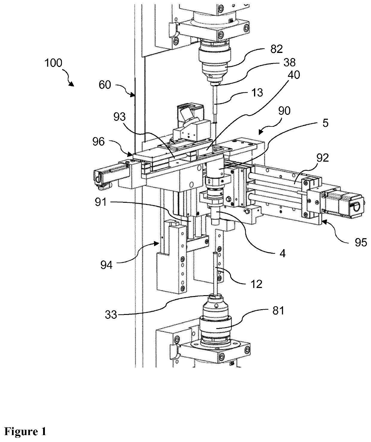
[0039]FIG. 1 shows an apparatus 100 according to an embodiment of the invention. The apparatus comprises a support, mount or framework 60, on which the mold units 4, 5, and the pressing punches 12, 13 are supported. The apparatus 100 comprises a displacement and positioning arrangement 90, which is configured to displaceably support one or more parts of the apparatus with respect to the framework 60. In an embodiment, one or more selected from the first mold unit 4, the s...


PUM

PropertyMeasurementUnit
wt %aaaaaaaaaa
wt %aaaaaaaaaa
temperaturesaaaaaaaaaa

Abstract

The present invention concerns a process for manufacturing a cutting tool, in particular a milling cutter, such as an end mill. The process comprises providing one or two partial molds. In an embodiment, two mold units are used, each mold unit comprising two openings. In accordance with this embodiment, the process comprises joining the two mold units so as to form a mold, and inserting at least one pressing punch through one of the remaining openings in order to press a metal, ceramic or carbide powder added to the mold. The pressed cutting tool can be ejected by way of a rotational ejection rod, which pushes the cutting tool out of the mold by way of a rotational, translational movement. The invention also concerns an apparatus for conducting the process.

Description

TECHNICAL FIELD[0001]The present invention relates to a process for manufacturing a cutting tool, a precursor cutting tool, a blank, and / or a cutting tool insert, to cutting tools, precursors, blanks and inserts obtained by the process and to an apparatus for conducting the process.BACKGROUND ART AND PROBLEMS SOLVED BY THE INVENTION[0002]Cutting tools such as end mills are typically manufactured by feeding a granulated material, such as a metal and / or carbide powder, into an extruder for pressing and extruding rods, hydrogen de-waxing, sintering, cutting, centerless grinding, flute grinding and coating. Different steps may be conducted by different manufacturers. The step-of dewaxing is typically conducted in a hydrogen furnace, and sintering in an HIP (hot isostatic pressing) furnace. In some cases, the flutes are subjected to honing before cleaning and coating.[0003]The cutting edges or flutes of the cutting tool are formed in the step of grinding the rod so as to obtain desired s...

Claims


Application Information

Patent Timeline
Patent Type & Authority Applications(United States)
IPC IPC(8): B22F3/03B22F5/06
CPCB22F2301/00B22F3/03B22F2005/001B22F5/06B30B15/022B30B11/02B30B15/32
Inventor MORIER, DANIEL
Owner LAMINA TECH
Why Eureka
Try Eureka