Blood Flow Rate Measurement System

a blood flow rate and measurement system technology, applied in the field of catheters, can solve problems such as high-risk cad patients, compromise blood pressure, and patients considered to be too high-risk for complications

Pending Publication Date: 2020-09-17
ABIOMED
View PDF15 Cites 9 Cited by
  • Summary
  • Abstract
  • Description
  • Claims
  • Application Information

AI Technical Summary

Problems solved by technology

However, some of these patients are considered to be too high-risk for complications that may occur during these procedures.
However, high-risk CAD patients that have also been diagnosed with advanced heart failure or severe heart valve disease are particularly vulnerable during CHIP procedures, due to weakened heart muscle, which compromises blood pressure and cannot pump blood efficiently to the body.

Method used


Image

  • Blood Flow Rate Measurement System
  • Blood Flow Rate Measurement System
  • Blood Flow Rate Measurement System

Examples


third embodiment

[0023]FIG. 7 is a detailed schematic diagram of the signal generator of FIG. 4, according to the present invention.

DETAILED DESCRIPTION OF SPECIFIC EMBODIMENTS

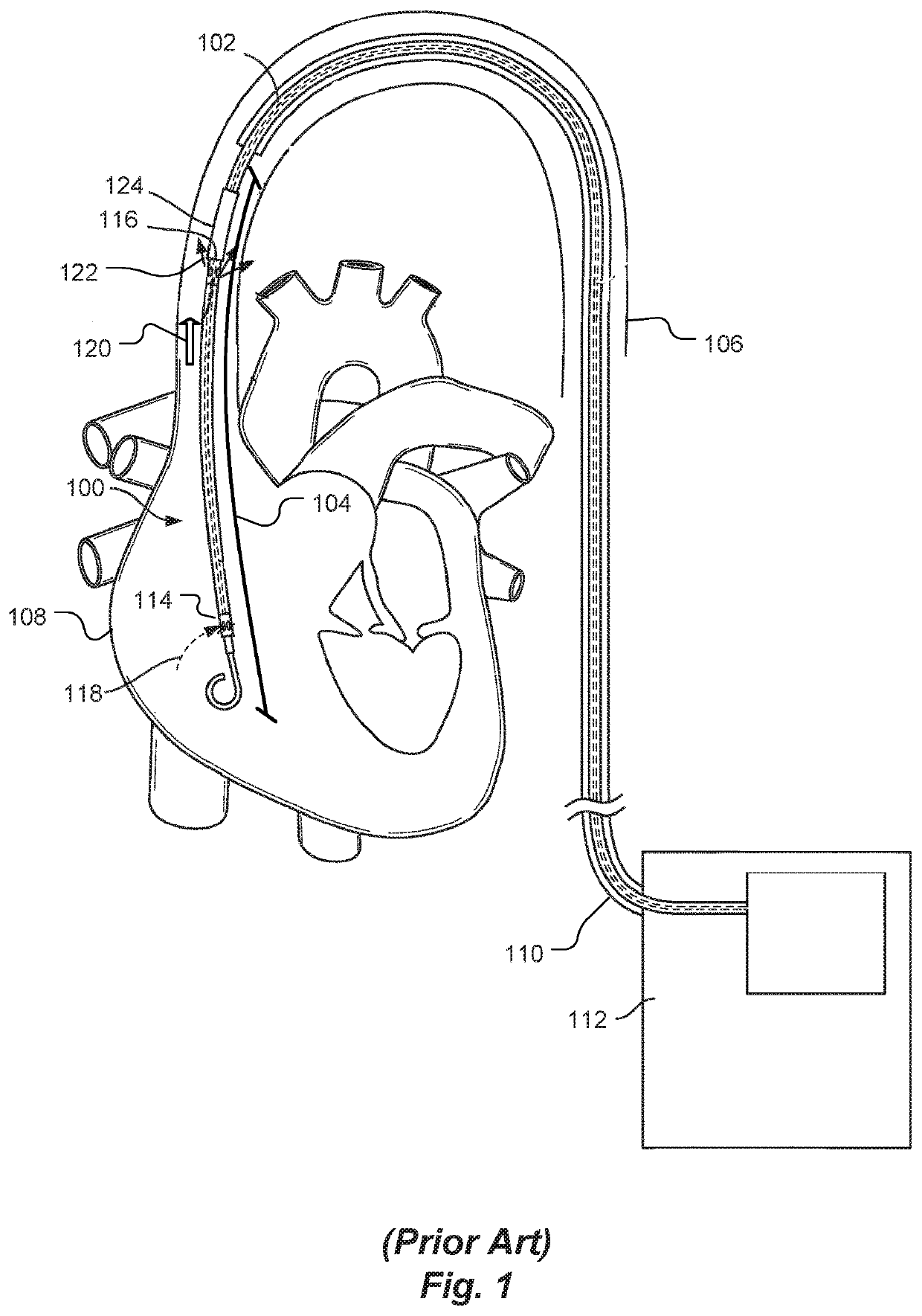
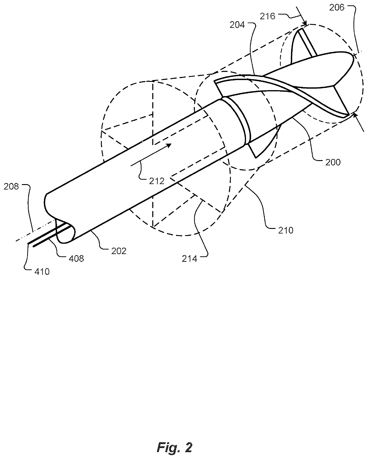
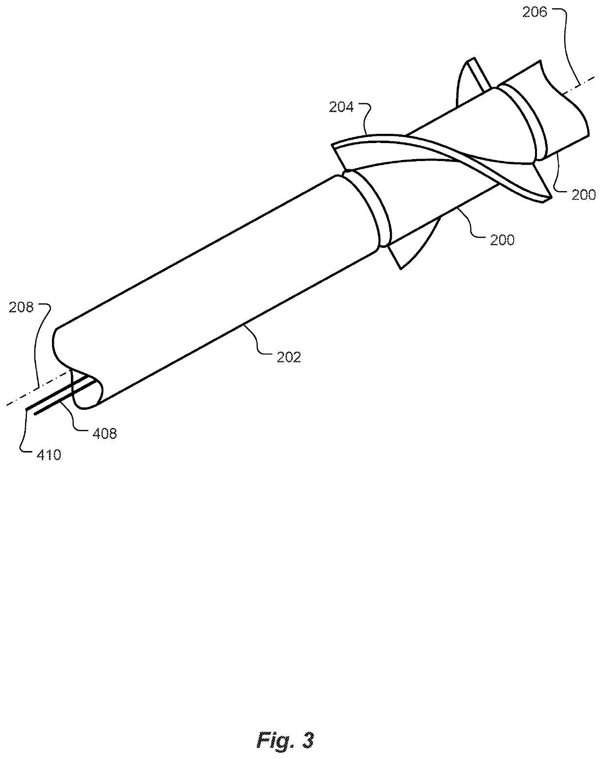
[0024]Embodiments of the present invention provide apparatus and methods for measuring blood flow, such as total blood flow due to natural heart action plus heart pump action, in a blood vessel of a patient when a catheter-based heart pump is inserted into the blood vessel, without relying on measurements of electric current drawn by a motor that drives the heart pump. Embodiments of the present invention include a turbine disposed at or near a distal end of the heart pump catheter. Rotation of the turbine blades is induced by blood or other fluid flowing through the blood vessel. The turbine is mechanically coupled to a signal generator, which generates a signal indicative of rotational speed of the turbine, which is dependent, at least in part, on speed of the fluid flowing through the blood vessel. The signal is carried by ...

first embodiment

[0035]In another embodiment, schematically illustrated in FIG. 6, the coil 504 (FIG. 5) is replaced by a Hall effect sensor 600. An output signal from the Hall effect sensor 600 may be processed by a threshold detector 602 (if needed) to generate the signal 404 indicative of the rotational speed of the turbine blades 204 (not shown in FIG. 6 for clarity). In this embodiment, the signal 404 consists of rectangular pulses 604. As with the first embodiment described with respect to FIG. 5, the frequency of the pulses 604 is proportional to the rotational speed of the blades 204.

[0036]In yet another embodiment, schematically illustrated in FIG. 7, the leads 408 and 410 from the coil 504 described with respect to FIG. 5 are connected to a light-emitting diode (LED) 700. The LED 700 is optically coupled to a distal end of an optical fiber 702. Each pulse (cycle) of the signal from the coil 504 causes the LED to flash, which sends an optical pulse along the optical fiber 702. A series of t...


PUM


Abstract

A blood flow rate measurement system measures fluid flow rate in a blood vessel having a catheter-based heart pump inserted therein, without relying on measurements of electric current drawn by a motor that drives the heart pump. A turbine is disposed at or near a distal end of the heart pump catheter. Blood or other fluid flowing through the blood vessel urges blades of the turbine to rotate. The turbine is mechanically coupled to a signal generator, which generates a signal indicative of a rotational speed of the turbine, which is dependent, at least in part, on speed of the fluid flowing through the blood vessel. A tachometer, external to the body of the patient, calculates the blood flow rate from the rotational speed of the turbine. In some cases, the blades are collapsible, to reduce diameter of the turbine, thereby facilitating insertion of the system into the blood vessel.

Description

BACKGROUNDTechnical Field[0001]The present invention relates to blood flow measurement systems and, more particularly, to catheter-mounted, turbine-driven blood flow measurement systems.Related Art[0002]Many patients with coronary artery disease (CAD) would benefit from stent percutaneous coronary intervention (CPI) or coronary artery bypass graft surgery. However, some of these patients are considered to be too high-risk for complications that may occur during these procedures. Risk factors include: advanced age; history of disease, such as kidney disease, stroke or diabetes; location of the CAD, including left main or bifurcated disease; challenging plaque types, including calcified or long lesions; chronic total occlusion of the coronary arteries; previous open-heart surgery; and advanced heart failure.[0003]Interventional cardiologists treat some of these high-risk patients with an advanced catheter-based procedure, referred to as complete or complex higher risk indicated percut...

Claims


Application Information

Patent Timeline
Patent Type & Authority Applications(United States)
IPC IPC(8): A61B5/027G01F1/075A61B5/00
CPCA61B5/6852G01F1/075A61B5/027A61B5/029A61M60/414A61M60/216A61M60/13A61M60/523A61M60/135A61M60/148A61M60/422A61M60/546A61M60/50A61M60/205
Inventor GOLDVASSER, DOV
Owner ABIOMED
Why Eureka
Try Eureka