
Method for wavefront measurement of optical imaging system based on grating shearing interferometry

a technology of optical imaging and wavefront measurement, applied in the field of optical measurement, can solve the problems of reducing the accuracy of phase retrieval, inconvenient measurement operation, and serious reducing phase retrieval precision, and achieve the effect of improving the accuracy of wavefront measurement of the optical imaging system to be tested and high diffraction orders

Active Publication Date: 2020-09-17
SHANGHAI INST OF OPTICS & FINE MECHANICS CHINESE ACAD OF SCI
View PDF0 Cites 2 Cited by
  • Summary
  • Abstract
  • Description
  • Claims
  • Application Information

AI Technical Summary

Benefits of technology

The present invention provides a method to measure the phase of an optical imaging system using a grating shearing interferometer system. The method can accurately measure the phase of the system by eliminating the influence of high-order diffraction beams and adjusting the shear ratio of the system. The method has high phase retrieval precision and a large measurable range of numerical aperture. The technical effect of the invention is to improve the accuracy of wavefront measurement and optical imaging system testing.

Problems solved by technology

However, interference of high-order other than ±1st-order beams and 0th-order beam still exists on the receiving surface of the detector, which seriously reduces the phase retrieval precision.
When the method is used for phase retrieval, a large number of system errors is introduced, which seriously reduces the phase retrieval accuracy.
The disadvantage of the method is that when the shear direction or the shear ratio is changed, the mask filter needs to be replaced synchronously, resulting in inconvenient measurement operation and increasing the complexity of the mechanical structure.
However, for the presence of ±7th- and higher-order diffraction beams, the method still cannot eliminate the effects of these high-order diffraction beams.

Method used


Image

  • Method for wavefront measurement of optical imaging system based on grating shearing interferometry
  • Method for wavefront measurement of optical imaging system based on grating shearing interferometry
  • Method for wavefront measurement of optical imaging system based on grating shearing interferometry

Examples


Embodiment Construction

[0025]In combination with the figures and the embodiment hereunder, the present invention will be described in detail, but the protection scope of the present invention is not limited to the figures and the embodiment described below.

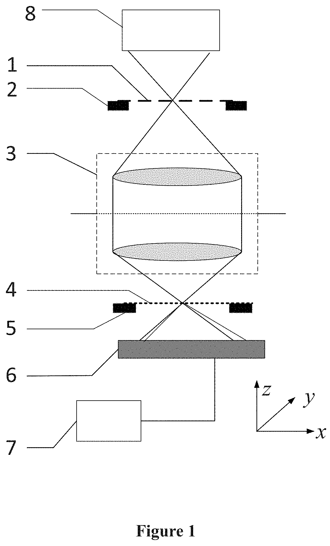
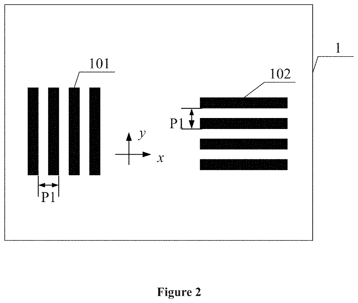
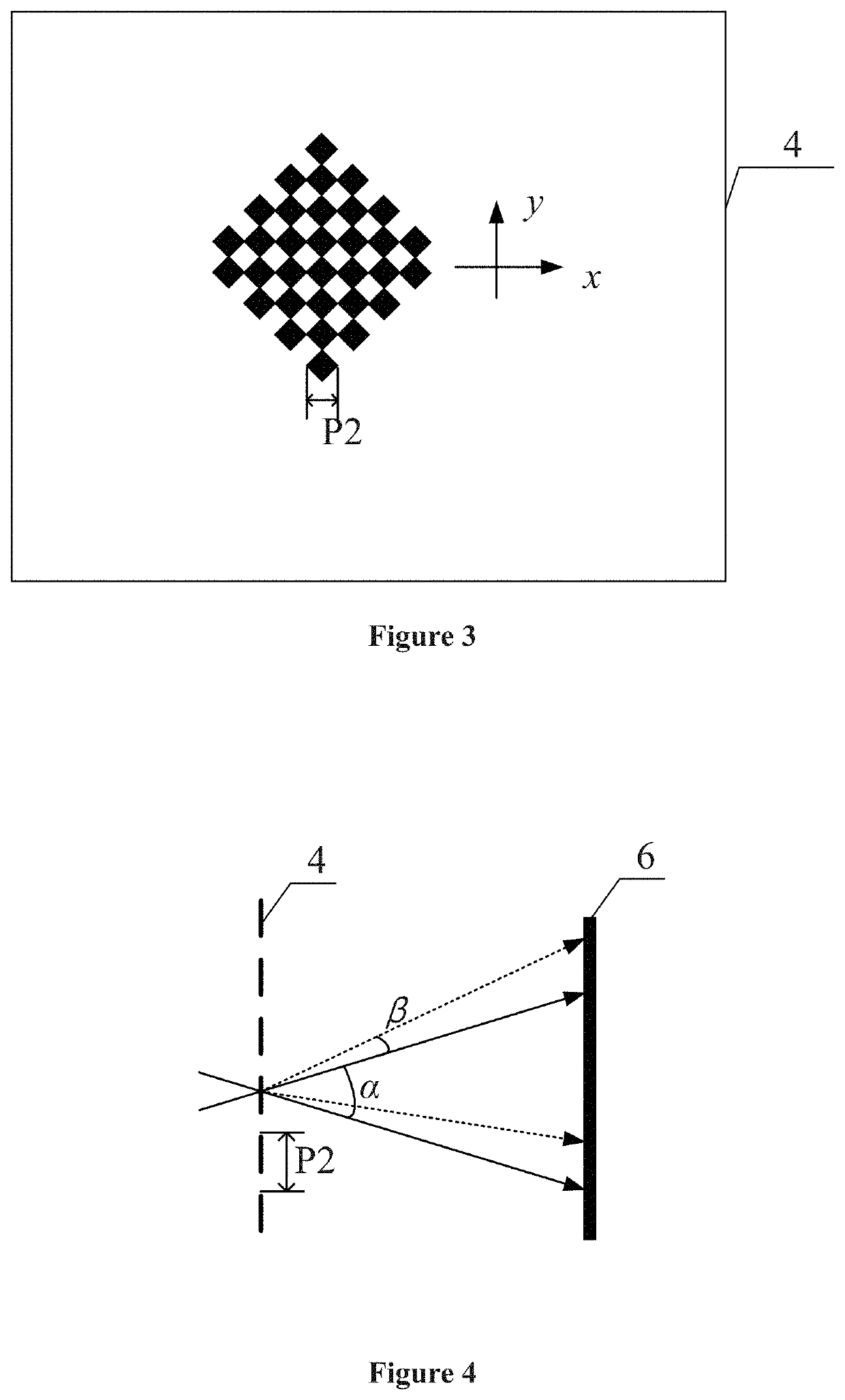
[0026]The grating shearing interferometer system used by the method for wavefront measurement of optical imaging system based on grating shearing interferometry disclosed in the present invention is shown in FIG. 1, and the system comprises a light source and illumination system 8, a one-dimensional diffraction grating plate 1, a first three-dimensional stage 2, a two-dimensional diffraction grating plate 4, a second three-dimensional stage 5, a two-dimensional photoelectric sensor 6, and a computing unit 7. The light source and the illumination system 8 output spatially incoherent light, the one-dimensional diffraction grating plate 1 is fixed on the first three-dimensional stage 2, the two-dimensional diffraction grating plate 4 is fixed on the second...


PUM

PropertyMeasurementUnit
light intensityaaaaaaaaaa
diagonal frequencyaaaaaaaaaa
frequencyaaaaaaaaaa

Abstract

A method for wavefront measurement of optical imaging system based on grating shearing interferometry, the grating shearing interferometer comprising: a light source and illumination system, an optical imaging system to be tested, a one-dimensional diffraction grating plate, a two-dimensional diffraction grating plate, a two-dimensional photoelectric sensor and a computing unit. The one-dimensional diffraction grating plate and the two-dimensional diffraction grating plate are respectively placed on the object side and the image side of the optical imaging system to be tested. By collecting N sets of interferograms with a2πNphase-shifting interval (where,N=2(fix(ceil(1 / s)2)+1),s is the shear ratio of the grating shearing interferometer), combined with a certain phase retrieval algorithm, the influence of all high-order diffraction beams on the phase retrieval accuracy is eliminated, and finally the wavefront measurement accuracy for the optical imaging system is improved.

Description

CROSS-REFERENCE TO RELATED APPLICATION[0001]The subject application claims priority on Chinese patent application no. CN 201910183243.6 filed on Mar. 12, 2019 in China. The contents and subject matter of the Chinese priority application is incorporated herein by reference.FIELD OF TECHNOLOGY[0002]The present invention relates to optical measurement, particularly, a phase retrieval algorithm and device for wavefront measurement of the projection lens of lithography or other optical imaging system that are based on grating shearing interferometry.BACKGROUND ART[0003]The grating shearing interferometer has the advantages of common path, no need for extra ideal reference, high precision, high sensitivity, and simple structure. The phase-shifting interferometry is introduced, where a series of interferograms with different phase-shifting amounts are acquired by moving the grating laterally, and then the wavefront aberration of the system under test is obtained.[0004]For shearing interfer...

Claims


Application Information

Patent Timeline
Patent Type & Authority Applications(United States)
IPC IPC(8): G01B9/02G01J9/02
CPCG01B9/02034G01J9/0215G01M11/0271G01J2009/0219G03F7/706
Inventor LU, YUNJUNTANG, FENGWANG, XIANGZHAO
Owner SHANGHAI INST OF OPTICS & FINE MECHANICS CHINESE ACAD OF SCI
Learn More