Systems and methods for logging data in harsh environments

a technology of logging equipment and environment, applied in the direction of temperature measurement of flowing materials, instruments, heat measurement, etc., can solve the problems of inability to prevent moisture ingress into the capsule, and inability to protect electronic components

Active Publication Date: 2020-09-24
MAXIM INTEGRATED PROD INC
View PDF10 Cites 0 Cited by
  • Summary
  • Abstract
  • Description
  • Claims
  • Application Information

AI Technical Summary

Problems solved by technology

Typically, the capsule is not hermetic and cannot protect the electronic components under harsh environments, such as autoclave for steam sterilization at high pressure and high temperature.
Some of the conventional devices are designed to operate at high temperature environments, but cannot prevent the ingress of moisture into the capsule that damages the electronic components.
As such, the conventional devices can survive only a few sterilization cycles at best and thus are not suitable for logging data during multiple cycles.
When a conventional device for logging temperature data is placed inside the autoclave, the device may not be able to keep up with the temperature change due to the thermal resistance of the capsule material.
The thermal resistance may result in false reading of the ambient gas temperature.
However, the conventional chemical indicator cannot be used to trace the temperature as a function of time during the sterilization cycle.
However, in reality, they are all killed before a half cycle due to the stress of the temperature ramp up conditions.
In addition, the biological indicator has a long turnaround time since the spore sample may need to be sent to a lab and, depending on the type of spores, incubation may be needed.
Furthermore, the conventional CI and BI techniques require manual recording of paper logbooks, which is less efficient and more costly than electronic recording and processing of the logged data.

Method used


Image

  • Systems and methods for logging data in harsh environments
  • Systems and methods for logging data in harsh environments
  • Systems and methods for logging data in harsh environments

Examples


Embodiment Construction

[0020]In the following description, for the purposes of explanation, specific details are set forth in order to provide an understanding of the invention. It will be apparent, however, to one skilled in the art that the invention can be practiced without these details. One skilled in the art will recognize that embodiments of the present invention, described below, may be performed in a variety of ways and using a variety of means. Those skilled in the art will also recognize additional modifications, applications, and embodiments are within the scope thereof, as are additional fields in which the invention may provide utility. Accordingly, the embodiments described below are illustrative of specific embodiments of the invention and are meant to avoid obscuring the invention.

[0021]A reference in the specification to “one embodiment” or “an embodiment” means that a particular feature, structure, characteristic, or function described in connection with the embodiment is included in at...


PUM

PropertyMeasurementUnit
temperatureaaaaaaaaaa
pressureaaaaaaaaaa
temperatureaaaaaaaaaa

Abstract

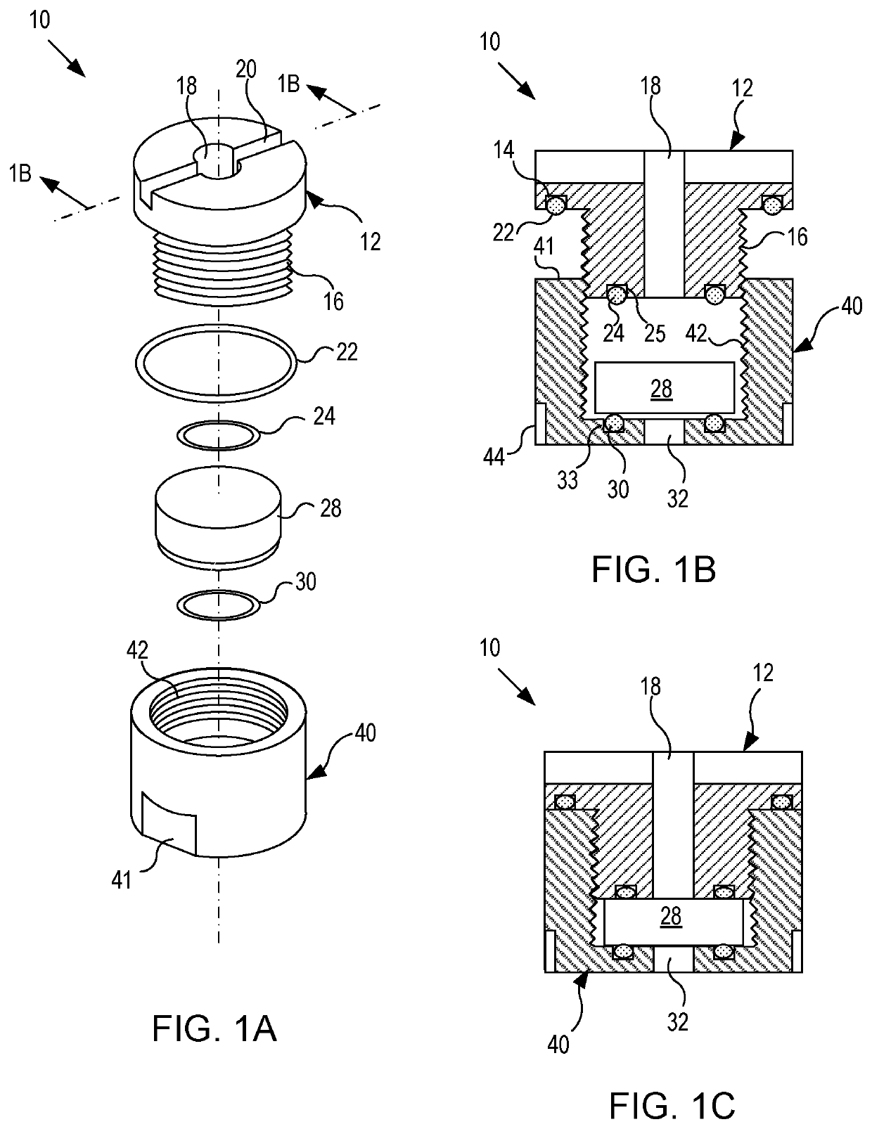
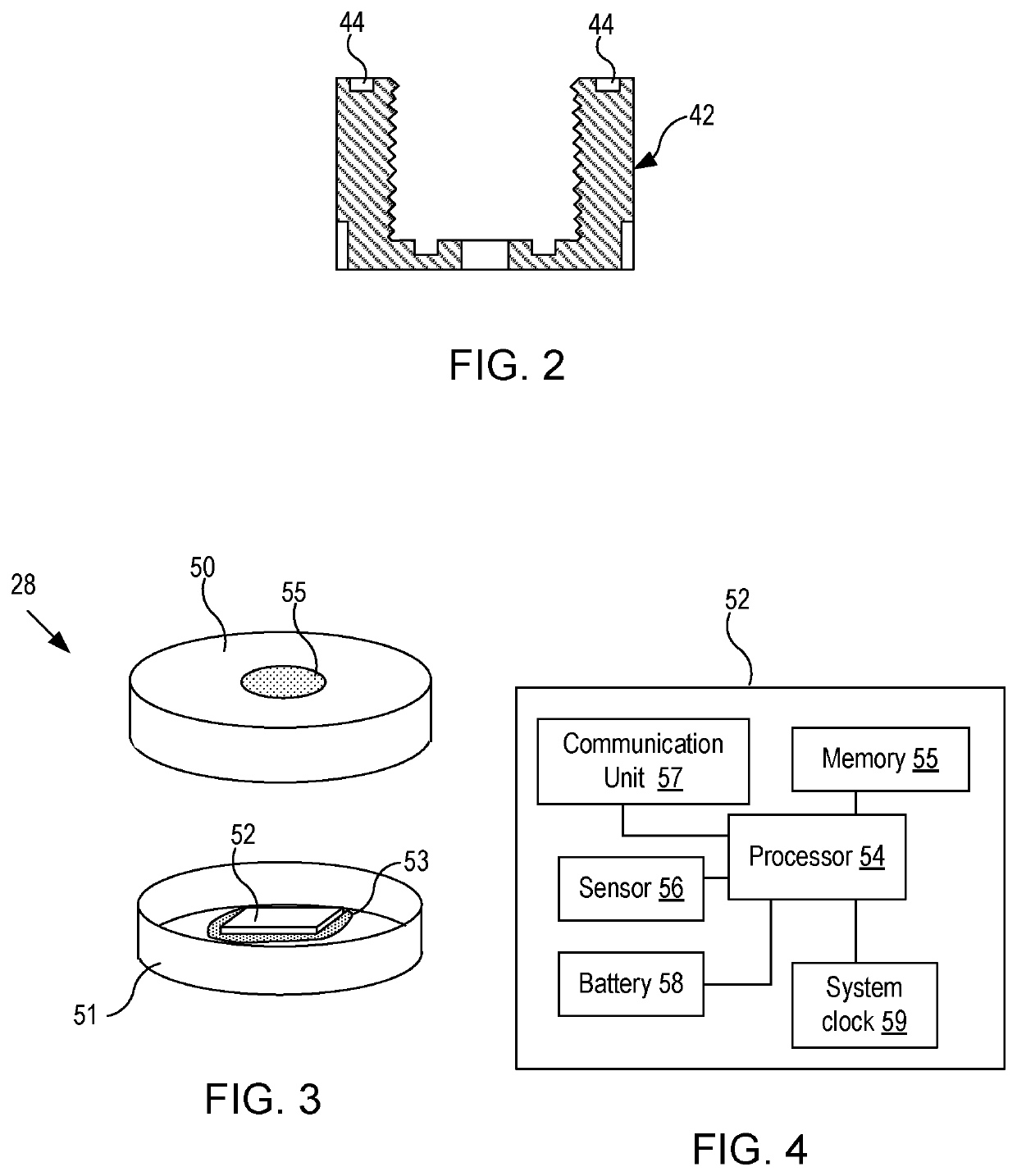
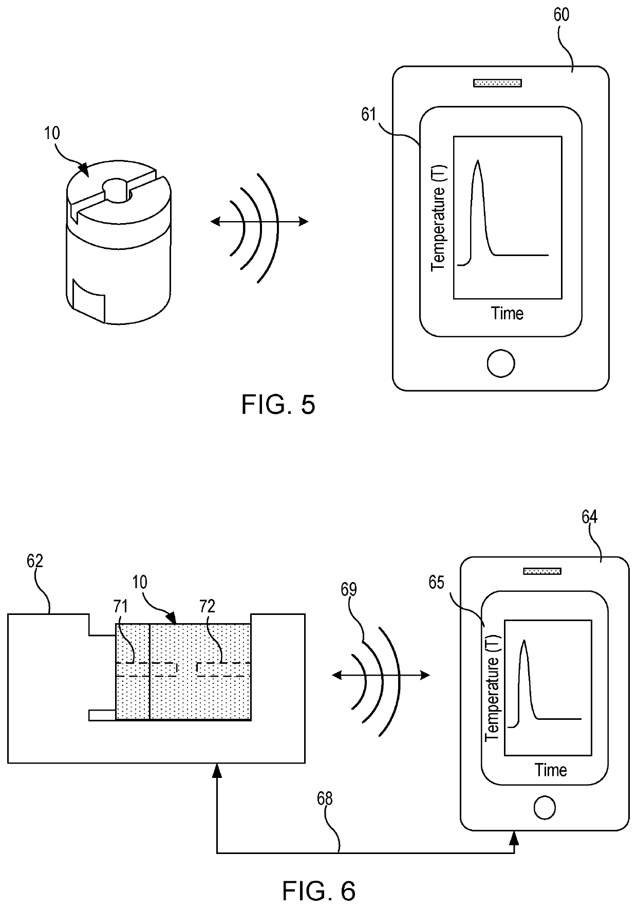
Systems and methods of the present invention allow to determine ambient gas temperature in harsh environments such as in a steam autoclave chamber during a sterilization process. In certain embodiments of the invention, temperature data is gathered using a sensor that is placed in an enclosed electronics-based temperature logging device. A capsule seals the temperature logging device except for a through hole that, during regular operation, allows gas to directly contact a surface of the temperature logging device in order to reduce a time lag between the data logging device and an ambient gas. As a result, the data logging device accurately can track temperature variations when placed, for example, inside a chamber.

Description

CROSS REFERENCE TO RELATED PATENT APPLICATIONS[0001]The present application claims priority benefit, under 35 U.S.C. § 119(e), to co-pending and commonly assigned U.S. Provisional Patent Application No. 62 / 261,749, entitled “APPARATUS FOR LOGGING DATA IN HARSH ENVIRONMENTS,” naming as inventors Jeffery Alan Gordon, Scott Edward Jones, and Hal Kurkowski (Docket No. 20057-1993P), U.S. Provisional Patent Application No. 62 / 261,782, entitled, “INDICATOR OF STERILIZATION EFFICACY USING A DATA LOGGER WITH CLOUD / SOFTWARE APPLICATION,” naming as inventors Michael James D'Onofrio, Carlos Manuel Contreras, and Raghunath Puttaiah (Docket No. 20057-1994P), and U.S. Provisional Patent Application No. 62 / 261,783, entitled “ALGORITHM TO CORRECT LAG BETWEEN INTERNAL TEMPERATURE SENSOR AND AMBIENT GAS,” naming as inventors Victor Levi, Michael James D'Onofrio, and Raghunath Puttaiah (Docket No. 20057-1995P), which applications were filed Dec. 1, 2015, and are hereby incorporated herein by reference ...

Claims


Application Information

Patent Timeline
Patent Type & Authority Applications(United States)
IPC IPC(8): G01K1/08G01K1/02G01K13/02G06F11/34A61L2/28
CPCA61L2/28G01K1/08G01K1/022G06F11/3476G01K13/02G01K7/42G01K7/015
Inventor GORDON, JEFFERY ALANJONES, SCOTT EDWARDKURKOWSKI, HAL
Owner MAXIM INTEGRATED PROD INC
Why Eureka
Try Eureka