Articulating moored profiler system
a profiler and mooring technology, applied in special-purpose vessels, instruments, vessels, etc., can solve the problems of limited functionality, limited profile over time, and limited sampling depth, so as to reduce drag, minimize power consumption, and reduce drag
- Summary
- Abstract
- Description
- Claims
- Application Information
AI Technical Summary
Benefits of technology
Problems solved by technology
Method used
Image
Examples
example 1
[0077]The drag of the AMP was estimated and compared to estimates of the drag of the McLane Moored Profiler (“MMP”) from the prior art. The drags were estimated for a state with 30 cm / s current while the profiler is traveling along the mooring mechanism at 30 cm / s. Much of the drag of the MMP and most of the drag of the AMP is from the bluff cable guides, guide wheels, drive motor, CTD, and acoustic current sensor. When there is zero current, these bluff bodies are in line, and the downstream bodies are in the wakes of the upstream bodies, reducing drag. When the current is 30 cm / s, each bluff body is in fresh flow and does not benefit from wake shading.
[0078]The total MMP drag is estimated to be 8.6 N of which 6.1 N is in the direction of profiler movement. The MMP body drag is estimated to be 3.8 N. The AMP as described herein used a low-drag body in the longitudinal vessel body 102, which is streamlined and pointed into the flow, keeping the boundary layer attached. The bare body...
example 2
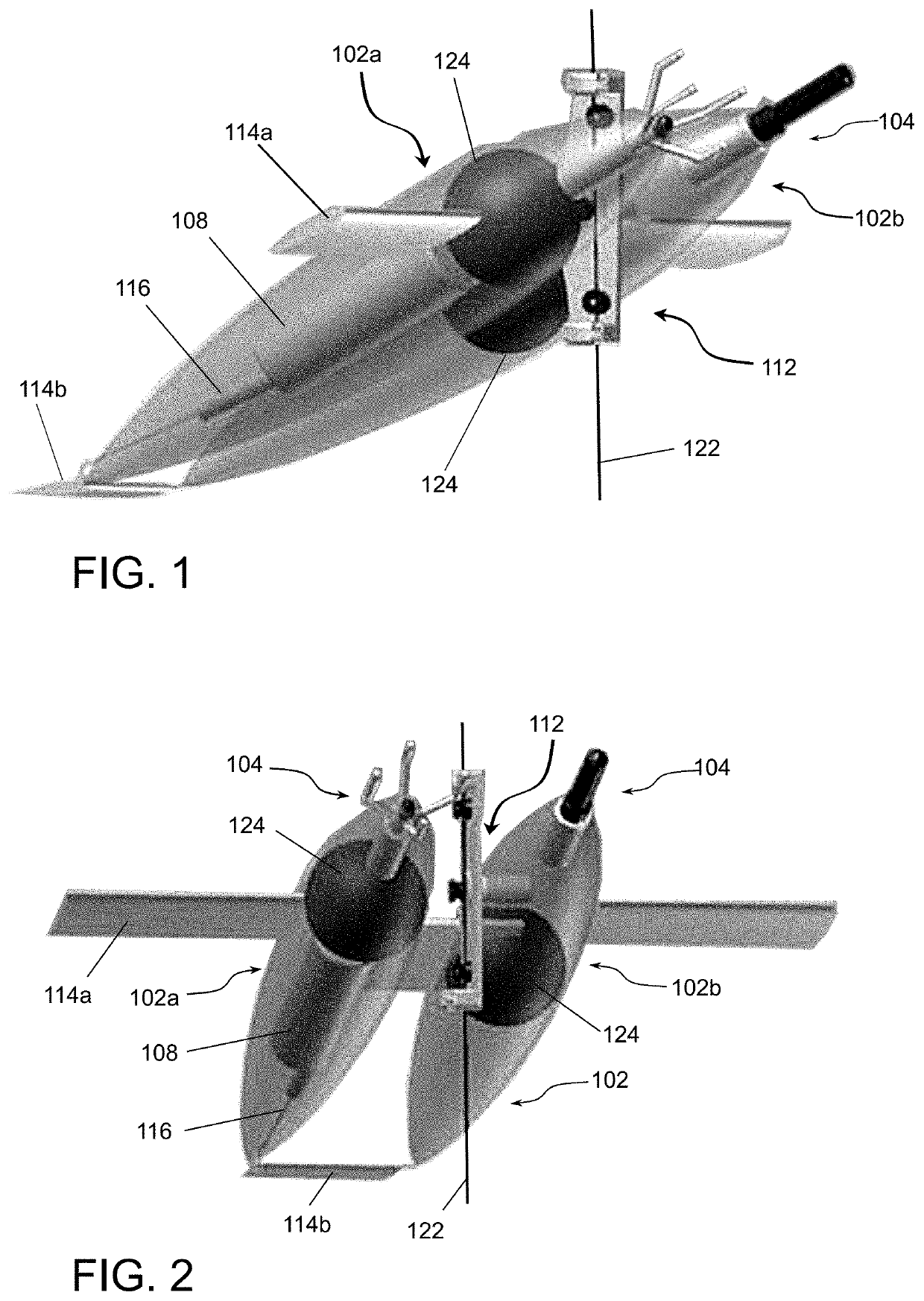
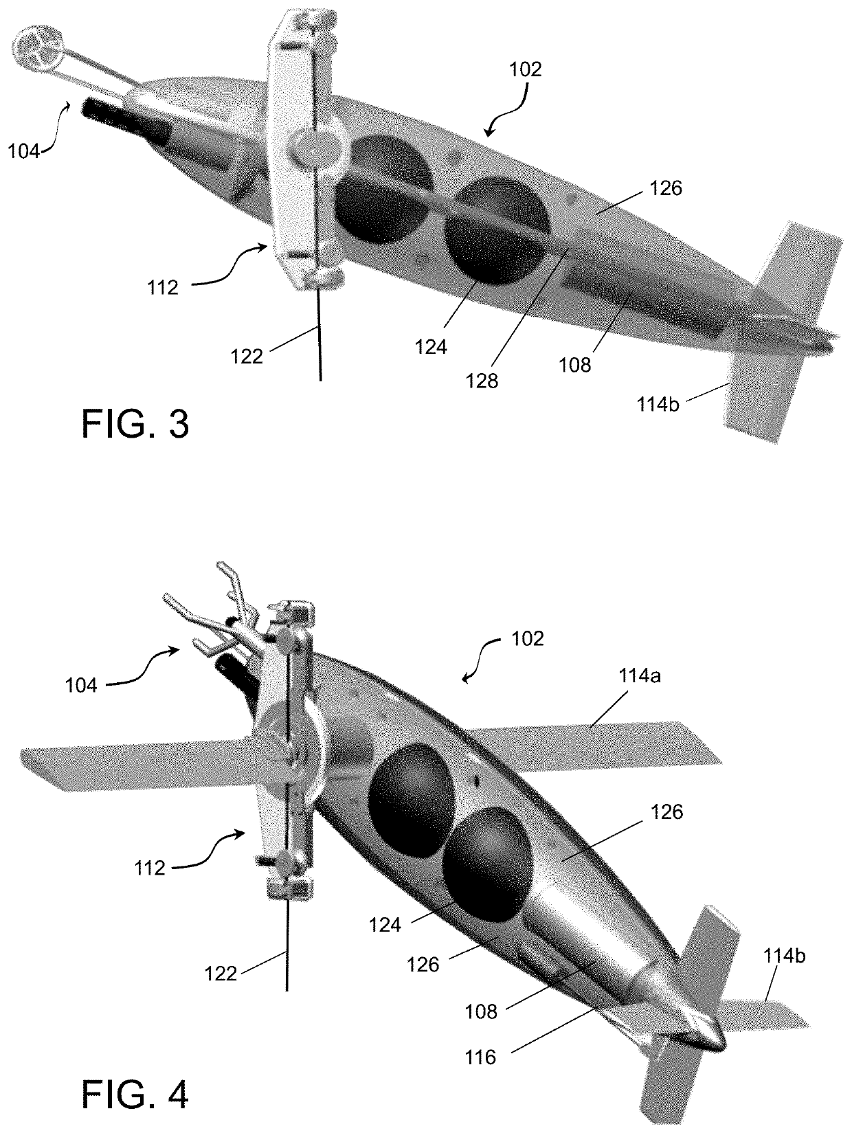
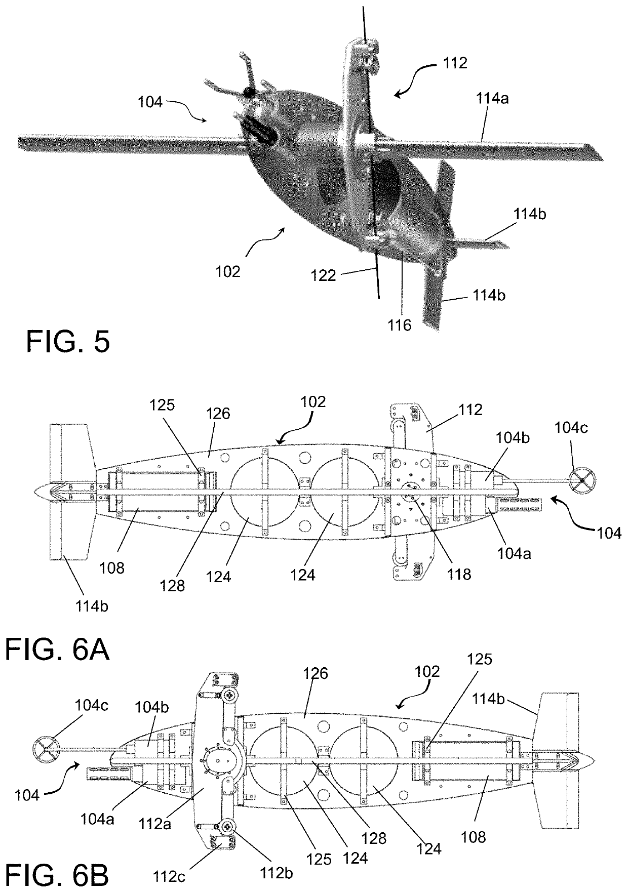
[0083]As depicted in FIGS. 1 and 2, this embodiment of the inventive device employs two vessel bodies 102a and 102b coupled together spatially separated by a connection near the middle sections of the bodies 102a and 102b. This connection is capable of providing electrical signals, power, data communication, etc. between the two vessel bodies 102a and 102b or may only provide a mechanical engagement between the two bodies. The mooring mechanism 122 is typically disposed between the two bodies and engaged with the attachment mechanism 112.
[0084]Vessel body 102a is adapted to incorporate the electronics housing 108 and the lift control system 116 within the internal space. As shown, the buoyancy sphere within vessel body 102a is shifted forward relative to buoyancy sphere in vessel body 102b to compensate for the difference in weight distribution. The position of the buoyancy spheres 124, needs to account both for the overall buoyancy / weight and fore-aft balance about the pivoting poi...
example 3
AMP Specifications
[0085]The following table lists specification for one embodiment of the present invention. While the materials listed are suitable, other materials of similar properties may be used. For example, many structural components are comprised of ultra-high molecular weight (UHMW) polyethylene but may be substituted for a material with similar properties including high abrasion resistance, high melt viscosity, low coefficient of friction, chemical resistance, load-bearing strength, and impact strength.
TABLE 1DimensionsLength85.0 inWidth17 inSensor ArraySensorsCTD SensorMAVS SensorDrag (at 1080 cm / s current)Total Device Drag3.5NVessel Body Drag0.2NProfiling SpeedUp / Down25 cm / s-35 cm / sDepth RatingTypical Use6,500 mMaterialsShell⅛″ PolyethyleneElectronics HousingTitaniumVertical Plate1″ UHMW PolyethyleneHorizontal Plate1″ UHMW PolyethyleneTruck Plate1″ UHMW PolyethyleneIdler Arm Support1″ UHMW PolyethyleneIdler Arm Tab¼″ UHMW PolyethyleneDrive EngineErtalyte ®Drive WheelErta...
PUM
 Abstract
Description
Claims
Application Information
 - R&D
- Intellectual Property
- Life Sciences
- Materials
- Tech Scout
- Unparalleled Data Quality
- Higher Quality Content
- 60% Fewer Hallucinations
Browse by: Latest US Patents, China's latest patents, Technical Efficacy Thesaurus, Application Domain, Technology Topic, Popular Technical Reports.
© 2025 PatSnap. All rights reserved.Legal|Privacy policy|Modern Slavery Act Transparency Statement|Sitemap|About US| Contact US: help@patsnap.com


