
A direct liquid cooling system for cooling of electronic components

a technology of electronic components and liquid cooling system, which is applied in the direction of electrical equipment, lighting and heating apparatus, instruments, etc., can solve the problems of affecting the structural integrity affecting the heat generation efficiency of computing and electronic system, and various errors in computing and electronic system

Active Publication Date: 2020-10-08
INPRO TECH LLC
View PDF0 Cites 8 Cited by
  • Summary
  • Abstract
  • Description
  • Claims
  • Application Information

AI Technical Summary

Benefits of technology

The system has a pump that pushes a coolant through the electronic components, which prevents them from overheating and malfunctioning. This system helps to cool down electronic components and keeps them running smoothly.

Problems solved by technology

It is well known that heat is a major problem facing the computer and electronic industries.
Additionally, operation at high temperatures can cause power fluctuations and failures that lead to various errors within the computing and electronic systems.
If the heat dissipation is not consistently managed heat will inevitably harm the structural and data integrity of the computing and electronic system.
Given the limited footprint of many computing and electronic systems, a continuous increase in the number of heat generating components within the limited space creates challenging heat related issues.
To sufficiently cool a few high power components, very high airflow rates and / or large and / or expensive heat sinks are needed.
However, pure air-cooled systems have a high cost and noise impact, because of high cost associated with powerful high speed fans that operate at high noise levels.
As the packaging densities increase, the air cooling solutions are becoming more prohibitive, costly and ineffective.
In addition, air cooling has other associated costs in the form of unwanted acoustic and energy consumption.
Moreover, this approach is rising the dust accumulation within the enclosure which leads to the static electricity problems and radiation properties of surfaces degradation.
In large “data centers” that house many computing and electronic systems in close proximity, the heat dissipation issue is aggravated even more.
In such cases, cooling costs and feasibility of providing air cooling have become especially burdensome.
In general, electronic components of higher performing servers dissipate correspondingly more power.
Consequently, as energy costs and power dissipation continue to increase, the total cost of cooling a data center has also increased.
Such a low cooling capacity can significantly add to the cost of building a data center, since data centers can cost as much as about $250 per-square-foot to construct.
As the air-cooling example implies, commercially available methods of cooling have not kept pace with increasing server and data-center performance needs, or the corresponding growth in heat density.
As a consequence, adding new servers to existing data centers has become difficult and complex given the effort expended to facilitate additional power dissipation, such as by increasing an existing data center's air conditioning capacity.
Various alternative approaches for cooling data centers and their servers, e.g., using liquid cooling systems, have met with limited success.
For example, attempts to displace heat from a microprocessor for remotely cooling the chip have been expensive and cumbersome.
Accordingly, these liquid-cooling systems have been designed for particular component layouts and have been unable to achieve large-enough economies of scale to become commercially viable.
Immersion cooling of electronic components has been attempted in high-performance applications, but has not enjoyed widespread commercial success.
Such systems have been expensive, and offered by a limited number of suppliers.
One particular problem in systems disclosed in the above references is the necessity of draining the cooling coolant whenever physical access to the electronic modules was required.
In general, such an operation, besides being time consuming, requires the entire system to be switched off, especially if the component requiring attention is an essential element in the system architecture, such as the central processing unit (“CPU”).
Accordingly, each method of server or computer cooling currently employed or previously attempted have been prohibitively expensive and / or insufficient to meet increasing cooling demands of computing components.

Method used


Image

  • A direct liquid cooling system for cooling of electronic components
  • A direct liquid cooling system for cooling of electronic components
  • A direct liquid cooling system for cooling of electronic components

Examples


Embodiment Construction

[0048]Aspects of the invention are disclosed in the following description and related drawings directed to specific embodiments of the invention. Alternate embodiments may be devised without departing from the scope of the invention. Additionally, well-known elements of the invention will not be described in detail or will be omitted so as not to obscure the relevant details of the invention.

[0049]The word “exemplary” is used herein to mean “serving as an example, instance, or illustration.” Any embodiment described herein as “exemplary” is not necessarily to be construed as preferred or advantageous over other embodiments. Likewise, the term “embodiments of the invention” does not require that all embodiments of the invention include the discussed feature, advantage or mode of operation.

[0050]The terminology used herein is for the purpose of describing particular embodiments only and is not intended to be limiting of embodiments of the invention. As used herein, the singular forms ...


PUM


Abstract

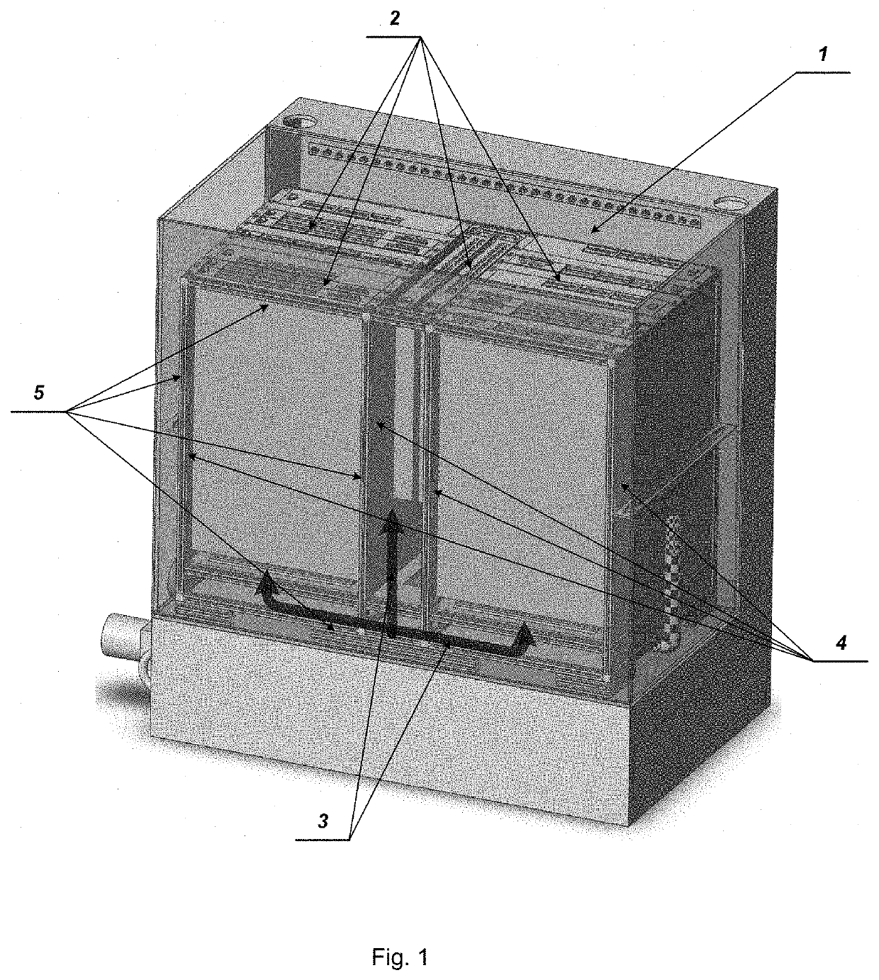
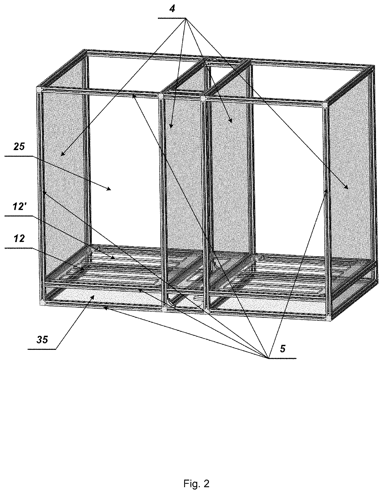
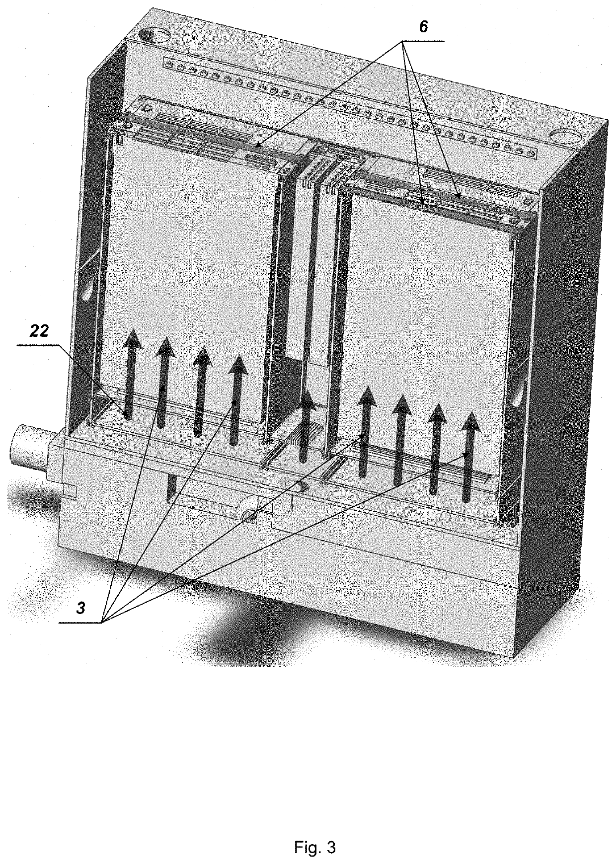
The present disclosure is directed to a direct liquid cooling system for cooling of electronic components and configured to maintain a predetermined thermostable environment for the electronic components. The system includes a reservoir and a rack removably placed in the reservoir and securely containing electronic components to be cooled. The system also includes a dielectric coolant which is configured to flow upward in parallel streams between the electronic components and a pump that facilitates continuous pumping of the dielectric coolant thereby forcing the dielectric coolant upwards through the electronic components and overflowing the dielectric coolant within the reservoir. A heat exchanger is also provided and coupled with the reservoir via an outlet pipeline. Additionally, a controller is provided to monitor the temperature of the dielectric coolant and adjust the flow of the coolant.

Description

BACKGROUND OF THE INVENTIONField of the Invention[0001]The present disclosure relates to a cooling of electronic components, and in particular, to a direct liquid cooling system for cooling of electronic components, which is designed to create a predetermined thermostable environment for various electronic components.Description of the Background Art[0002]It is well known that heat is a major problem facing the computer and electronic industries. All electronic components produce heat, and in general the faster they process information, the more heat they produce.[0003]It is known, the higher the temperature of operation of the electronic components, the shorter the components' life expectancy. Additionally, operation at high temperatures can cause power fluctuations and failures that lead to various errors within the computing and electronic systems. If the heat dissipation is not consistently managed heat will inevitably harm the structural and data integrity of the computing and ...

Claims


Application Information

Patent Timeline
Patent Type & Authority Applications(United States)
IPC IPC(8): H05K7/20F28F27/00F28F9/22H05K7/14
CPCH05K7/20272F28F27/00H05K7/20781H05K7/1488F28F9/22H05K7/20281H05K7/20236G12B15/04H05K7/20
Inventor BILAN, ALEXEY PETROVICHZHILKO, VIKTOR YURIEVICHKAUFMAN, VIKTOR MIKHAILOVICHNIKITIN, ALEXANDER NIKOLAEVICH
Owner INPRO TECH LLC
Learn More