Simultaneous Fault Detection and Location of Power Distribution Systems

a power distribution system and simultaneous technology, applied in the field of electric power systems, can solve the problems of increasing the cost of electricity generation, the burden on electric utilities to make the most of the existing power system, and the complexity of fault detection and location in the distribution system than in the transmission system, so as to reduce the use of the central processing unit (cpu) in the system and power consumption, and the effect of quick detection of faults in the power distribution system

Active Publication Date: 2020-10-15
MITSUBISHI ELECTRIC RES LAB INC +1
View PDF1 Cites 23 Cited by
  • Summary
  • Abstract
  • Description
  • Claims
  • Application Information

AI Technical Summary

Benefits of technology

[0010]In accordance with embodiments of the present invention, it become possible for fault detection system to quickly detect faults in the power distribution system even when the computation process of detecting faults is increasingly scaled with the complexity of fault events on the power distribution system. This also provides advantages that can reduce central processing unit (CPU) usage in the system and power consumption, which improves the performance of the processor(s).

Problems solved by technology

As energy consumers keep on increasing their demands and further upgrading of existing equipment is always limited, electric utilities are forced to make the most out of the existing power systems.
Fault detection and location is more complex in distribution systems than transmission systems, due to a huge number of feeders and laterals, less available measurement, the networks being unbalanced and / or mixed-phase, etc.
Another key issue is the increasing deployment of distributed generators.
The downside of distributed generator usage is when faults occur, and fault currents can then have more than one source, and making fault detection and location more complicated.
What makes fault location and detection an even more complex problem is that distribution networks are often formed without any intentional grounding—they are formed as ungrounded distribution networks.
As a result, it is very hard to detect these types of faults, allowing the network to continue normally with its operations until a second fault occurs.
Unfortunately, this family poses complications under complex topologies.
Unfortunately, all prior of arts have limitations, for example, they are only applicable for single fault detections, difficult to deal with systems with distributed generations, and required additional devices.

Method used


Image

  • Simultaneous Fault Detection and Location of Power Distribution Systems
  • Simultaneous Fault Detection and Location of Power Distribution Systems
  • Simultaneous Fault Detection and Location of Power Distribution Systems

Examples


example

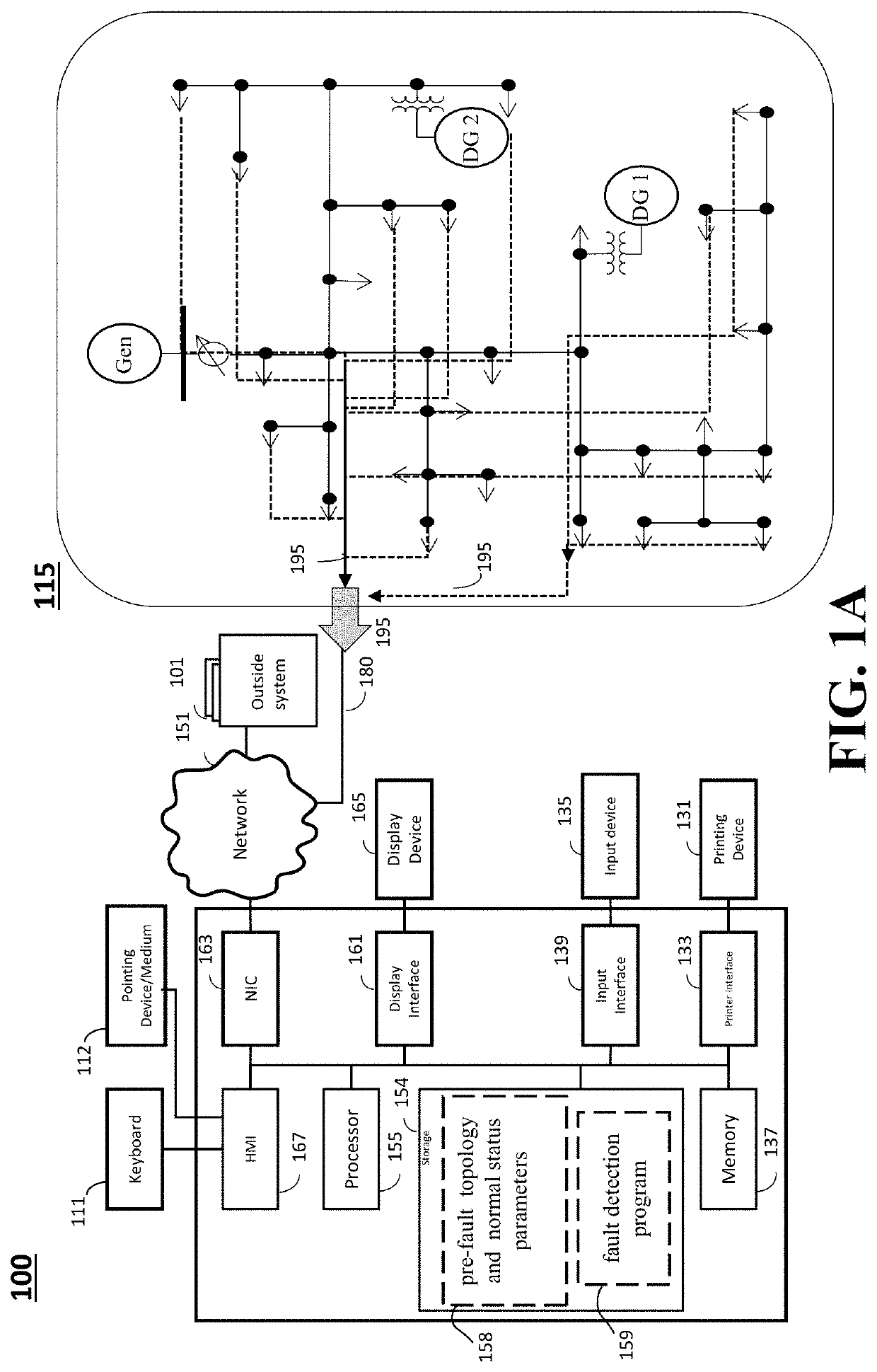
[0137]FIG. 7 is a 36-bus sample system with a 4.8 kV operating voltage. It shows the one-line diagram for the sample system. The system includes a swing generator 717, denoted Gen, is attached to bus 799, a PQ distributed generator, denoted DG 1, 757A is attached to bus 731, and a PV distributed generator, denoted DG 2, 757B is attached to bus 706. The entire network is ungrounded, as all loads 777 are ungrounded, and all generators 717, 757A and 757B are connected with transformers or voltage regulators from the network using Wye / Delta connection, 767. All line sections 747 are of three-phase.

[0138]The first example simulates two ground faults occurred at different times. The first fault is a phase a to ground fault occurred at section 744-727 at point 0.1500 (denoted x) at time 0.1 s, and the second fault is a phase b to ground fault occurred at section 711-740 at point 0.6000 (denoted y) at time 0.2 s. All buses 744, 727, 711 and 740 are equipped with current and voltage measurin...


PUM


Abstract

Systems and methods are configured for detecting and locating simultaneous faults in a distribution network having primary and secondary buses connected with two-terminal sections. The measured three-phase voltages and currents from the primary buses are received via a communication network, and the series impedances and shunt admittances and the pre-fault connectivity topology are retrieved from the storage. Simultaneous faults are determined to occur by verifying at least one phase of at least three buses having phase current mismatches determined as the differences between the measured values and calculated values using normal topology and phase voltages that are greater than a threshold. A location for each fault is determined individually if the faults are occurring at non-adjacent sections in the distribution network, or jointly if the faults are occurring at adjacent sections in the distribution network. Faulted line sections are isolated by activating switching operations for connected switches to the faulted line sections that communicatively linked to distribution system grid via communication network.

Description

FIELD OF THE INVENTION[0001]The present disclosure relates generally to electric power systems, and more particularly to simultaneous fault detection and location of power distribution systems.BACKGROUND OF THE INVENTION[0002]As energy consumers keep on increasing their demands and further upgrading of existing equipment is always limited, electric utilities are forced to make the most out of the existing power systems. One of the main goals expected from the consumers is to have an electric power system with continuous supply of energy, higher reliability and minimal outages. To tackle this, utilities look to decrease the number of faults in a system or, more realistically, be able to detect and locate them as fast as possible. By doing so, customer outage times and economic loss are reduced, reliability is improved and thus makes maintenance and operation easier.[0003]Fault detection and location is more complex in distribution systems than transmission systems, due to a huge numb...

Claims


Application Information

Patent Timeline
Patent Type & Authority Applications(United States)
IPC IPC(8): G01R31/08H02H7/22H02H1/00
CPCH02H1/0007G01R31/086H02H1/0092H02H7/22H02J3/0012H02J13/00001H02J13/00002H02J13/00006Y02E60/00Y04S10/30Y04S10/40Y04S10/52Y04S40/12
Inventor SUN, HONGBOSVENDA, VANJATAKANO, TOMIHIRO
Owner MITSUBISHI ELECTRIC RES LAB INC
Why Eureka
Try Eureka