
Device for capacitive measurements in a multi-phase medium

a multi-phase medium and capacitive measurement technology, applied in the direction of level indicators by physical variable measurement, liquid/fluent solid measurement, instruments, etc., can solve the problems of unsatisfactory prior-art devices, achieve high impedance, improve accuracy, and facilitate the effect of reaching

Active Publication Date: 2020-10-29
UNIV GRENOBLE ALPES
View PDF6 Cites 2 Cited by
  • Summary
  • Abstract
  • Description
  • Claims
  • Application Information

AI Technical Summary

Benefits of technology

This patent describes a system that improves the reliability and accuracy of detecting the presence of different phases in a vessel. It uses capacitive measurements to determine the height of sedimented or floating layers in a multiphase medium, which may change over time. This system allows for valid capacitive measurements to be taken even when the height of the medium is not constant. This helps to accurately determine the quality of the oil or other polluting phase in a sewage treatment plant or other applications, and ensures that only the necessary amount of polluting phase is removed, reducing the risk of pollution in the environment.

Problems solved by technology

This prior-art device is not entirely satisfactory in so far as it requires a particular geometric arrangement of the excitation electrodes, and, in particular, the spacing therebetween to be larger than or equal to two times the thickness of the dielectric walls of a vessel containing the multiphase medium (see claim 1; column 5, lines 21-25; column 6, lines 4-5).

Method used


Image

  • Device for capacitive measurements in a multi-phase medium
  • Device for capacitive measurements in a multi-phase medium
  • Device for capacitive measurements in a multi-phase medium

Examples


examples of embodiments

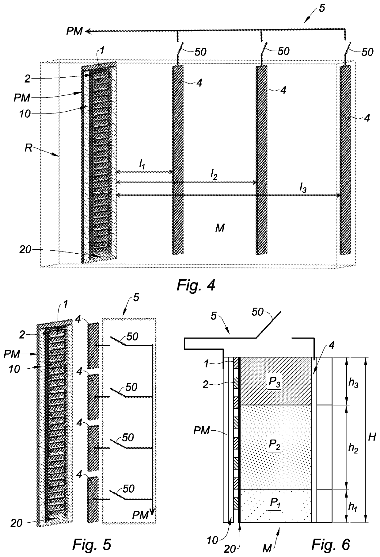
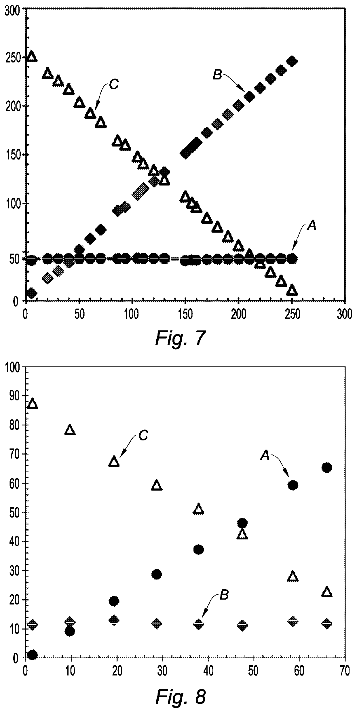
[0139]As illustrated in FIGS. 7 and 8, tests were performed on a multiphase medium M containing an aqueous phase A, an oil phase B and an air phase C in a vessel R consisting of a test-tube of a height H.

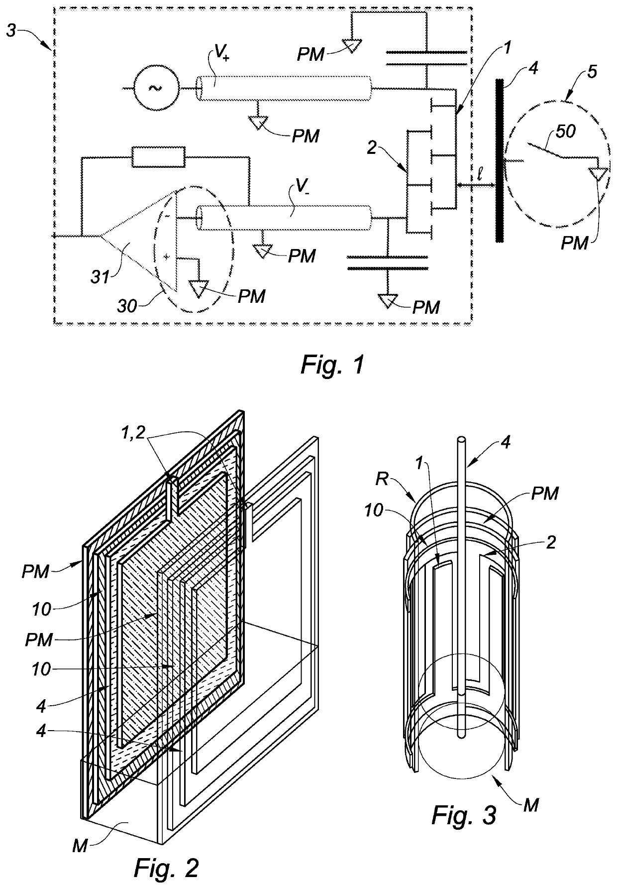
[0140]The capacitor was formed by a pair of interdigitated excitation electrodes 1, 2. Each excitation electrode 1, 2 had a width of 250 μm. The inter-electrode distance was 250 μm. The capacitor had a height of 300 mm. The capacitor extended over one face of a dielectric layer 10 made of polyimide. The dielectric layer 10 had a thickness of 25 μm. The pair of excitation electrodes 1, 2 was covered with a dielectric film 20 made of polyimide. The dielectric film 20 had a thickness of 25 μm.

[0141]The working frequency was 1 kHz. The transcapacitance between the pairs of excitation electrodes 1, 2 was measured using an LCR meter.

[0142]The calibration to determine the values CA,onH, CA,offH was carried out by filling a test-tube with water and by submerging the pair of excitation elect...


PUM

PropertyMeasurementUnit
frequencyaaaaaaaaaa
distanceaaaaaaaaaa
electrical potentialaaaaaaaaaa

Abstract

A device comprises at least one pair of excitation electrodes forming a capacitor; a floorplan (e.g., a ground plane); and an electronic circuit. The device comprises at least one control electrode arranged at a distance from the capacitor. A switching circuit, of the device, comprises a switch having an open state and a closed state. The switching circuit is designed to apply, to the control electrode, an electric potential common to the floorplan when the switch is in the closed state. The switching circuit is also designed to leave a floating electrical potential for the control electrode when the switch is in the open state. The electronic circuit is designed to measure the mutual capacitance between the pair of excitation electrodes when the switch is in the open state and when it is in the closed state.

Description

CROSS-REFERENCE TO RELATED APPLICATIONS[0001]This application is a national phase entry under 35 U.S.C. § 371 of International Patent Application PCT / FR2019 / 050033, filed Jan. 8, 2019, designating the United States of America and published as International Patent Publication WO 2019 / 138181 A1 on Jul. 18, 2019, which claims the benefit under Article 8 of the Patent Cooperation Treaty to French Patent Application Serial No. 1850268, filed Jan. 12, 2018.TECHNICAL FIELD[0002]The present disclosure relates to the technical field of devices for taking capacitive measurements of a multiphase medium, the multiphase medium containing fluid phases that differ in their dielectric properties, for example an aqueous phase and at least one organic phase.[0003]Devices for taking capacitive measurements have the advantage of being able to operate at a single working frequency, contrary to devices for taking impedance measurements (e.g., by electrochemical impedance spectroscopy), which require a co...

Claims


Application Information

Patent Timeline
Patent Type & Authority Applications(United States)
IPC IPC(8): G01F23/26G01R27/26G01D5/24
CPCG01R27/2605G01D5/2405G01F23/266G01F23/263
Inventor THIBAULT, PIERRE
Owner UNIV GRENOBLE ALPES
Learn More