Self-conducting light valve module and light valve heat dissipation device

Active Publication Date: 2020-10-29
NANHUA INTELLIGENT PRECISION MACHNE (SHENZHEN) CO LTD
View PDF0 Cites 2 Cited by
  • Summary
  • Abstract
  • Description
  • Claims
  • Application Information

AI Technical Summary

Benefits of technology

[0021]1. When the self-conducting light valve module of the present invention is placed in a light path of a projector, the LCD light valve will absorb part of the light and generate heat, wherein the first transparent graphene thermal conductive film and the second transparent graphene thermal conductive film can conduct the heat to edges thereof, as well as to the panel frame. The first transparent graphene thermal conductive film and the second transparent graphene thermal conductive film have ultra-high in-plane thermal conductivity coefficients, so the heat of the LCD light valve generated by absorbing light can be directly and quickly conducted to surfaces of the first transparent graphene thermal conductive film and the second transparent graphene thermal conductive film, and can be quickly transferred in an in-plane direction to the panel frame, which is conducive to rapid heat dissipation of the LCD light valve, thereby effectively improving a service life of the LCD light valve, and enabling the LCD light valve to adapt to stronger light irradiation.
[0022]2. The present invention can equalize temperatures of an entire transparent surface of the LCD light valve to a certain extent, so that temperature gradient differences within the transparent surface of the LCD light valve are reduce

Problems solved by technology

Relatively, the heat dissipation is most difficult for the light valve of an LCD projector, because heat dissipation function and light transmission function of the light valve overlap, which means the light valve performs not only heat dissipation, but also light transmission, so any opaque thermally conductive substance cannot be used to quickly conduct heat away by directly contacting the transparent surface of the light valves.
There have already been technologies that use crystal glass to conduct heat by directly contacting the the transparent surface of the light valve, but have very limited improvement in heat dissipation of the light valve, because thermal conductivity coefficient of the crystal glass, no matter in whi

Method used


Image

  • Self-conducting light valve module and light valve heat dissipation device
  • Self-conducting light valve module and light valve heat dissipation device
  • Self-conducting light valve module and light valve heat dissipation device

Examples


Example

Embodiment 2

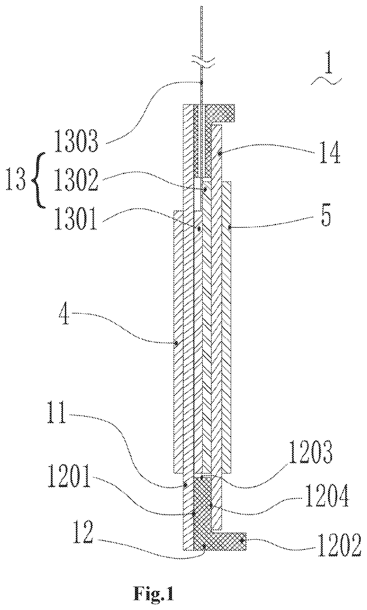
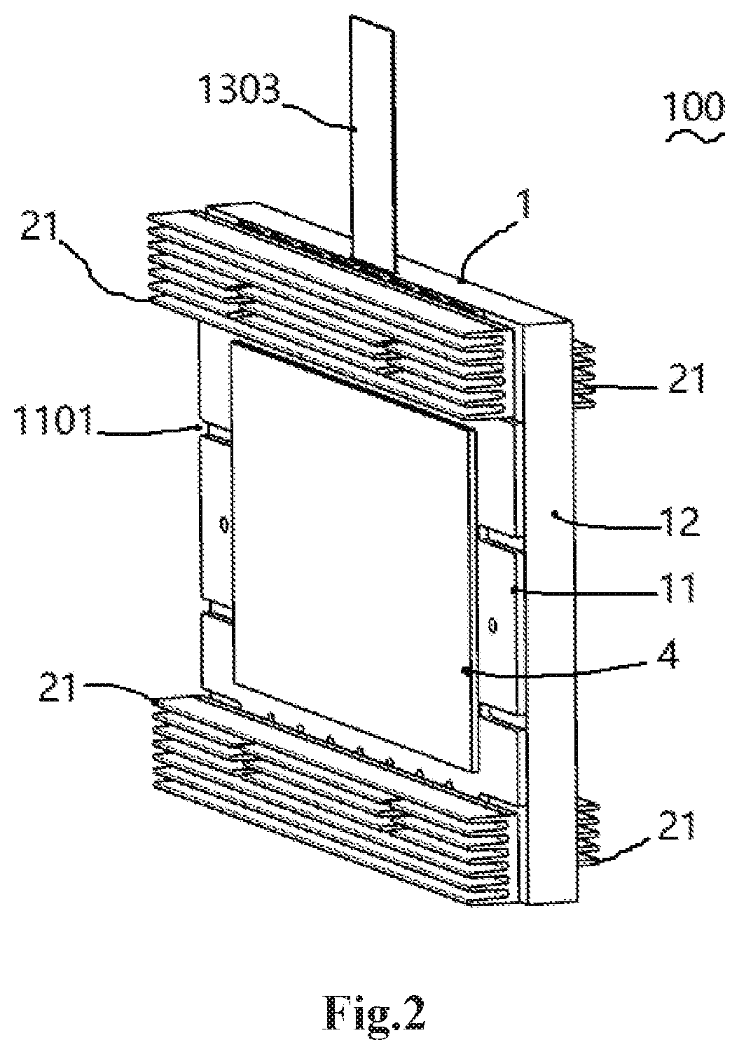
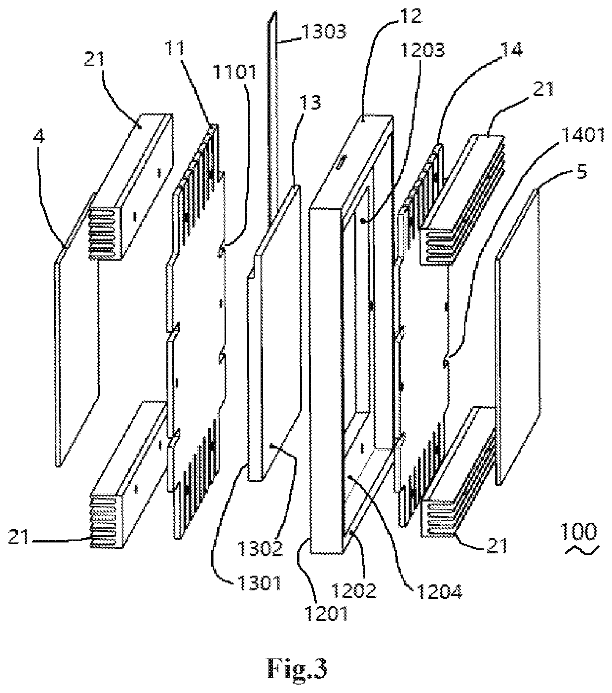
[0050]Referring to FIGS. 1-6, the present invention provides a light valve heat dissipation device 10, comprising a self-conducting light valve module 1 described above, and a heat diffusion device 2 installed on an external peripheral wall of the self-conducting light valve module 1; wherein heat of the self-conducting light valve module 1 is transferred to the heat diffusion device 2, and then diffused into air by the heat diffusion device 2.

[0051]According to the embodiment 2, the LCD light valve 13, the incident polarizer 4 and the emergent polarizer 5 absorb light and generate heat, wherein the heat can be directly and quickly conducted to surfaces of the first transparent graphene thermal conductive film 11 and the second transparent graphene thermal conductive film 14, and can be quickly transferred in an in-plane direction to the panel frame 12, and then diffused into air by the heat diffusion device 2, which is conducive to rapid heat dissipation of the LCD ligh...


PUM

PropertyMeasurementUnit
Electrical conductoraaaaaaaaaa
Transparencyaaaaaaaaaa
Thermal conductivityaaaaaaaaaa

Abstract

A self-conducting light valve module includes: a first transparent graphene thermal conductive film, a panel frame, an LCD light valve, and a second transparent graphene thermal conductive film; wherein the panel frame has a first plane and a second plane at two ends, respectively; a rectangular through hole is drilled at a center of the panel frame, and the LCD light valve is installed in the rectangular through hole; the first transparent graphene thermally conductive film is attached to the first plane and the incident surface of the LCD light valve; and the second transparent graphene thermally conductive film is attached to the second plane and the emergent surface of the LCD light valve. A light valve heat dissipation device includes: a heat diffusion device installed on an external peripheral wall of the self-conducting light valve module.

Description

CROSS REFERENCE OF RELATED APPLICATION[0001]The present invention claims priority under 35 U.S.C. 119(a-d) to CN 202010159916.7, filed Mar. 9, 2020.BACKGROUND OF THE PRESENT INVENTIONField of Invention[0002]The present invention relates to projector technologies, and more particularly to a self-conducting light valve module and a light valve heat dissipation device.Description of Related Arts[0003]When the lighting system of a projector illuminates the light valve, there is always a part of the light that is absorbed by the light valve and converted into Joule heat. The output brightness of the projector in the same optical system depends on how much light reaches the light valve. The higher the output brightness is required, the stronger the light irradiation should be on the light valve; and the stronger the light irradiation is, the more heat will be generated by the light valve. As a result, a stronger heat dissipation capacity is required to enable the light valve to work at a ...

Claims


Application Information

Patent Timeline
IPC IPC(8): G02F1/1333G02F1/1335G03B21/00G03B21/16
CPCG03B21/006G03B21/16G02F1/133382G02F1/133528H04N9/3144G02F1/133385C08K3/042H05K1/0204H05K7/2039H05K7/20963
Inventor GUO, HANWEN
Owner NANHUA INTELLIGENT PRECISION MACHNE (SHENZHEN) CO LTD
Why Eureka
Try Eureka