Electrochemical hydrogen compressor and method for operating electrochemical hydrogen compressor

a hydrogen compressor and electrochemical technology, applied in the direction of electrolysis components, electrochemical generators, chemistry apparatuses and processes, etc., can solve the problems of large pressure swing adsorption, impede the nation-wide installation of hydrogen stations, and the efficiency of hydrogen compression operation of electrochemical hydrogen compressors is not studied sufficiently, so as to improve the efficiency of hydrogen compression operation

Active Publication Date: 2020-10-29
PANASONIC INTELLECTUAL PROPERTY MANAGEMENT CO LTD
View PDF5 Cites 5 Cited by
  • Summary
  • Abstract
  • Description
  • Claims
  • Application Information

AI Technical Summary

Benefits of technology

[0009]One non-limiting and exemplary embodiment provides an electrochemical hydrogen compressor that can perform the hydrogen compression operation with improved efficiency as compared to the conventional example and a method for operating the electrochemical hydrogen compressor.
[0011]The electrochemical hydrogen compressor in the above aspect of the present disclosure has the effect of improving the efficiency of the hydrogen compression operation as compared to the conventional example.

Problems solved by technology

However, a problem in achieving widespread use of the fuel cell vehicles is how to provide an infrastructure for supplying hydrogen used as fuel and how to build hydrogen stations as many as possible over a wide area in the country.
However, the devices for pressure swing adsorption are large and require a huge installation cost, and this impedes nation-wide installation of hydrogen stations.
In the conventional example, an improvement in the efficiency of the hydrogen compression operation of the electrochemical hydrogen compressor is not studied sufficiently.

Method used


Image

  • Electrochemical hydrogen compressor and method for operating electrochemical hydrogen compressor
  • Electrochemical hydrogen compressor and method for operating electrochemical hydrogen compressor
  • Electrochemical hydrogen compressor and method for operating electrochemical hydrogen compressor

Examples


embodiment

[Structure of Electrochemical Hydrogen Compressor]

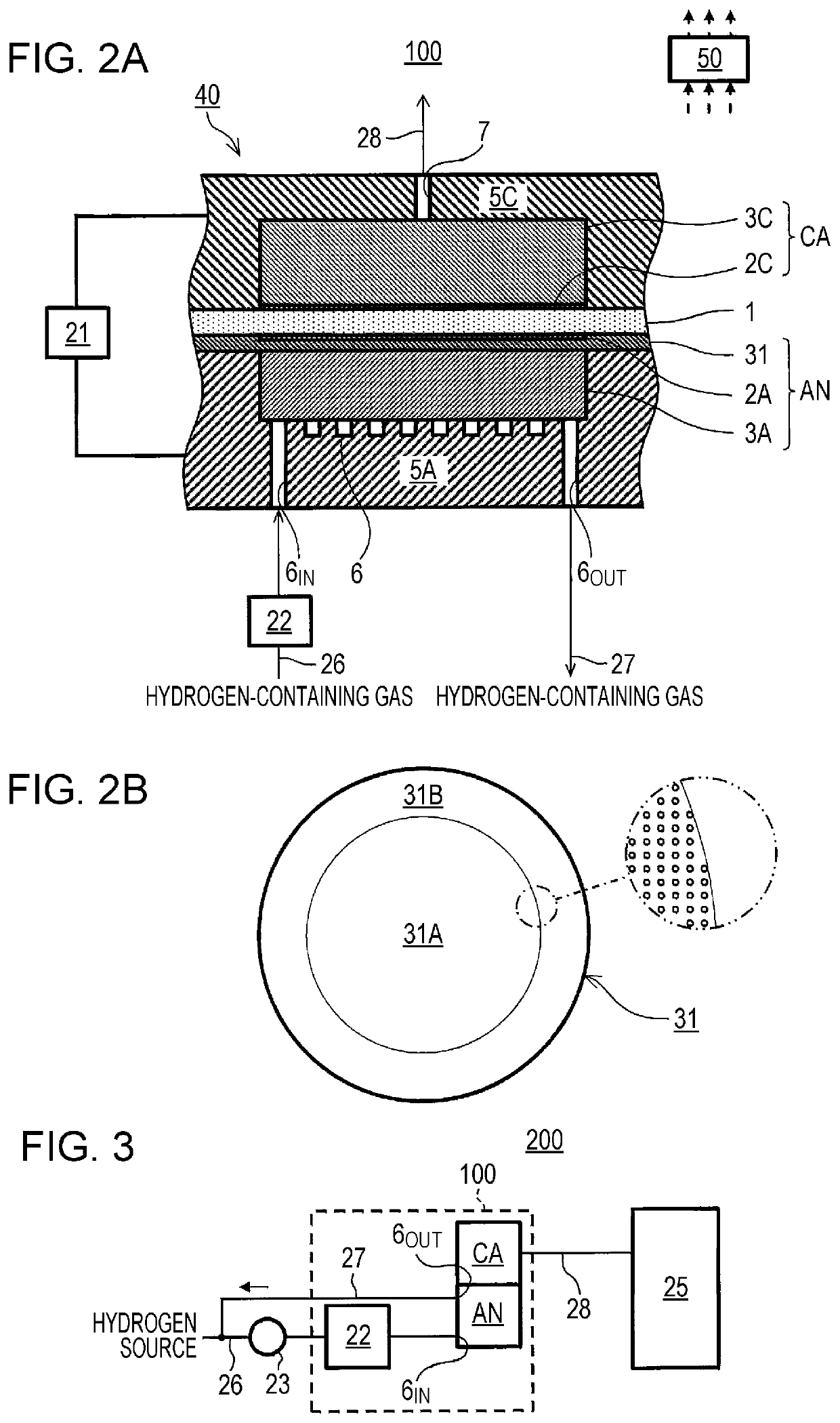
[0089]FIGS. 2A and 2B are illustrations showing an example of an electrochemical hydrogen compressor in the embodiment. FIG. 2B is a plan view of an anode gas diffuser plate 31 of the electrochemical hydrogen compressor 100.

[0090]In the example shown in FIGS. 2A and 2B, the electrochemical hydrogen compressor 100 includes a cell 40, a voltage applicator 21, a dew point adjuster 22, and a controller 50. The cell 40 of the electrochemical hydrogen compressor 100 includes an electrolyte membrane 1, an anode AN, a cathode CA, a cathode separator 5C, and an anode separator 5A.

[0091]The electrolyte membrane 1 is a membrane having a pair of principal surfaces and having proton (H+) conductivity. The electrolyte membrane 1 may have any structure so long as it has proton conductivity. Examples of the electrolyte membrane 1 include a fluorine-based polymer electrolyte membrane and a hydrocarbon-based electrolyte membrane. Specific examples of ...

first example

[0156]An electrochemical hydrogen compressor 100 in the present example is the same as the electrochemical hydrogen compressor 100 in the above embodiment except for the details of the following control by the controller 50.

[0157]The controller 50 controls the voltage applicator 21 such that part of the hydrogen in the hydrogen-containing gas supplied to the anode AN is compressed and the remaining part of the hydrogen is not compressed.

[0158]If the entire amount of the hydrogen in the hydrogen-containing gas supplied to the anode AN is compressed from the anode AN of the cell 40 to the cathode CA, an excessively large amount of condensed water may dwell in the anode AN, and flooding may occur in the anode AN. In this case, the diffusion overvoltage of the cell 40 of the electrochemical hydrogen compressor 100 may increase.

[0159]In the electrochemical hydrogen compressor 100 in the present example, part of the hydrogen in the hydrogen-containing gas supplied to the anode AN is recyc...

second example

[0168]An electrochemical hydrogen compressor 100 in the present example is the same as the electrochemical hydrogen compressor 100 in the embodiment except that the hydrogen-containing gas supplied to the anode AN contains a hydrogen-containing gas generated by water electrolysis.

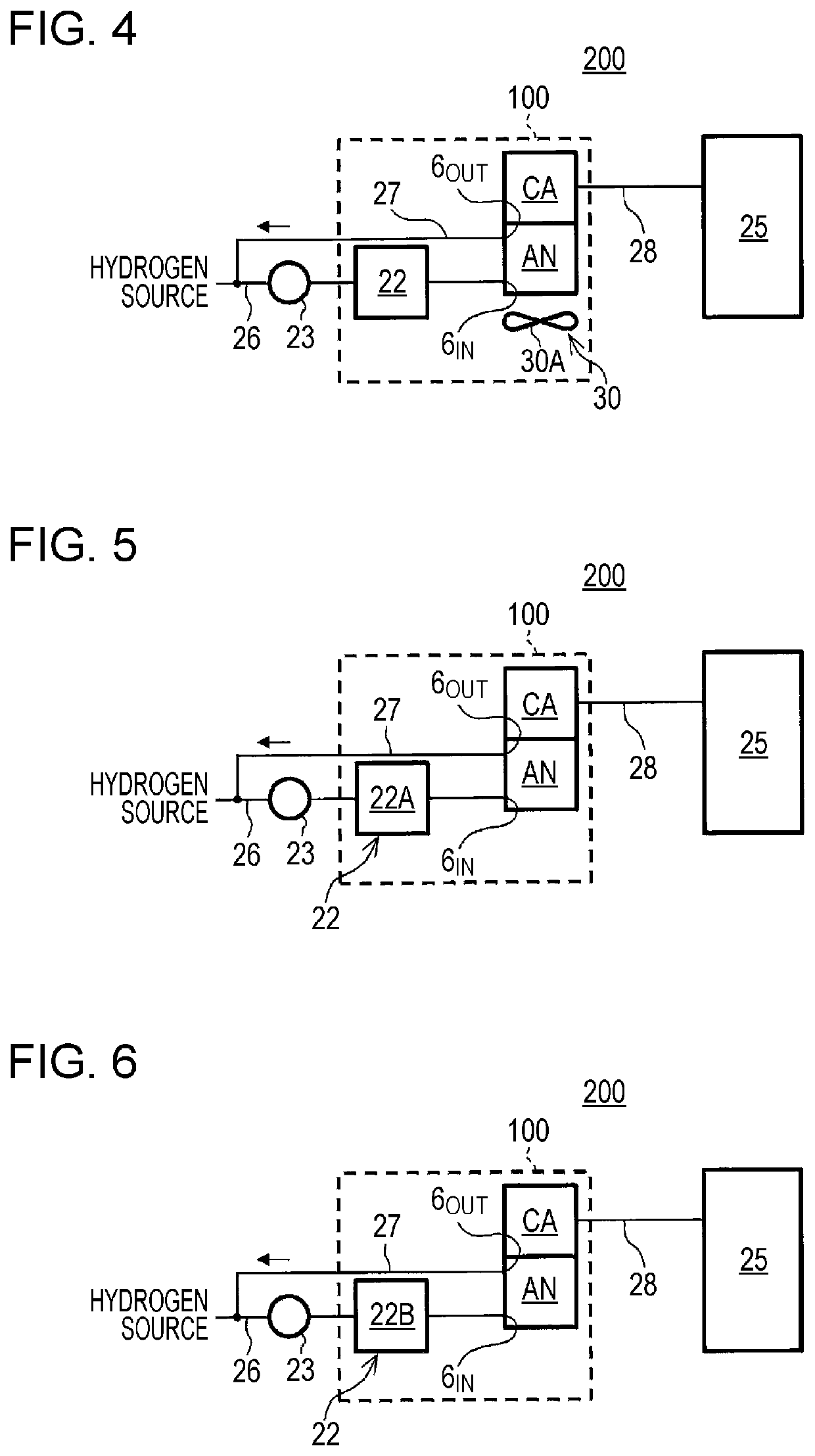
[0169]Specifically, in the present example, the hydrogen in the hydrogen source in FIG. 3 is generated by a water electrolysis device (not shown). The water electrolysis device may generate hydrogen using electric power generated from renewable energy such as sunlight. Any water electrolysis method may be used for the water electrolysis device. Examples of the water electrolysis in the water electrolysis device include solid polymer type water electrolysis.

[0170]The hydrogen-containing gas generated by water electrolysis contains water vapor. For example, the hydrogen-containing gas is in a high-humidity state with a dew point of about 80° C. Therefore, the electrochemical hydrogen compressor 100 in the pre...


PUM

PropertyMeasurementUnit
pressureaaaaaaaaaa
temperatureaaaaaaaaaa

Abstract

An electrochemical hydrogen compressor includes: a cell including a proton conductive electrolyte membrane having a pair of principal surfaces, a cathode disposed on a first one of the principal surfaces of the electrolyte membrane, and an anode disposed on a second one of the principal surfaces of the electrolyte membrane; a voltage applicator that applies a voltage between the anode and the cathode; a dew point adjuster that adjusts a dew point of a hydrogen-containing gas to be supplied to the anode; and a controller that, when the temperature of the cell increases, controls the dew point adjuster to increase the dew point of the hydrogen-containing gas.

Description

BACKGROUND1. Technical Field[0001]The present disclosure relates to an electrochemical hydrogen compressor and to a method for operating the electrochemical hydrogen compressor.2. Description of the Related Art[0002]From the viewpoint of improving fuel economy and of utilizing carbon-free fuel, fuel cell vehicles that run using electric power generated by fuel cells to drive motors have recently been receiving attention and have been put on the market.[0003]However, a problem in achieving widespread use of the fuel cell vehicles is how to provide an infrastructure for supplying hydrogen used as fuel and how to build hydrogen stations as many as possible over a wide area in the country. In conventional hydrogen stations, pressure swing adsorption (PSA), for example, is used to purify and compress hydrogen. However, the devices for pressure swing adsorption are large and require a huge installation cost, and this impedes nation-wide installation of hydrogen stations.[0004]In the comin...

Claims


Application Information

Patent Timeline
Patent Type & Authority Applications(United States)
IPC IPC(8): H01M8/04701C25B1/02C25B15/02C25B9/23
CPCC25B15/02H01M8/04738C25B1/02C25B9/00C01B3/00Y02E60/50C25B15/027C25B15/08C25B9/23
Inventor WAKITA, HIDENOBUYAKUMARU, YUUICHIUKAI, KUNIHIRO
Owner PANASONIC INTELLECTUAL PROPERTY MANAGEMENT CO LTD
Why Eureka
Try Eureka