Ultrasound diagnostic apparatus, method for controlling ultrasound diagnostic apparatus, and processor for ultrasound diagnostic apparatus

a diagnostic apparatus and ultrasound technology, applied in the field of ultrasound diagnostic apparatus, can solve the problems of high calculation load required for the detection of the intended site, difficulty for even an experienced user to visually check an ultrasound image, and difficulty in visually checking an ultrasound image, etc., to achieve easy and rapid detection of the target site

Pending Publication Date: 2020-11-05
FUJIFILM CORP
View PDF9 Cites 4 Cited by
  • Summary
  • Abstract
  • Description
  • Claims
  • Application Information

AI Technical Summary

Benefits of technology

[0027]According to the present invention, a memory that stores at least one peripheral site effective to detect a target site, and an operation guide unit that guides a user to operate an ultrasound probe so as to, during detection of the target site, detect the at least one peripheral site stored in the memory and that guides the user to operate the ultrasound probe so as to detect the target site on the basis of a recognition result obtained by a site recognition unit are included. This enables easy and rapid detection of the target site.

Problems solved by technology

However, the intended site has a structure similar to the structure of any other site, and it is therefore difficult for even an experienced user to visually check an ultrasound image obtained in accordance with the process flow described above to identify the intended site, which is problematic.
However, the calculation load required for the detection of the intended site is high, and an apparatus having high calculation performance is required to quickly detect the intended site.
For this reason, the medical image processing apparatus in JP2015-171437A may hinder the user from taking quick action in environments that require the user to take quick action, such as in emergency medical situations, and is thus unsuitable.

Method used


Image

  • Ultrasound diagnostic apparatus, method for controlling ultrasound diagnostic apparatus, and processor for ultrasound diagnostic apparatus
  • Ultrasound diagnostic apparatus, method for controlling ultrasound diagnostic apparatus, and processor for ultrasound diagnostic apparatus
  • Ultrasound diagnostic apparatus, method for controlling ultrasound diagnostic apparatus, and processor for ultrasound diagnostic apparatus

Examples


embodiment 1

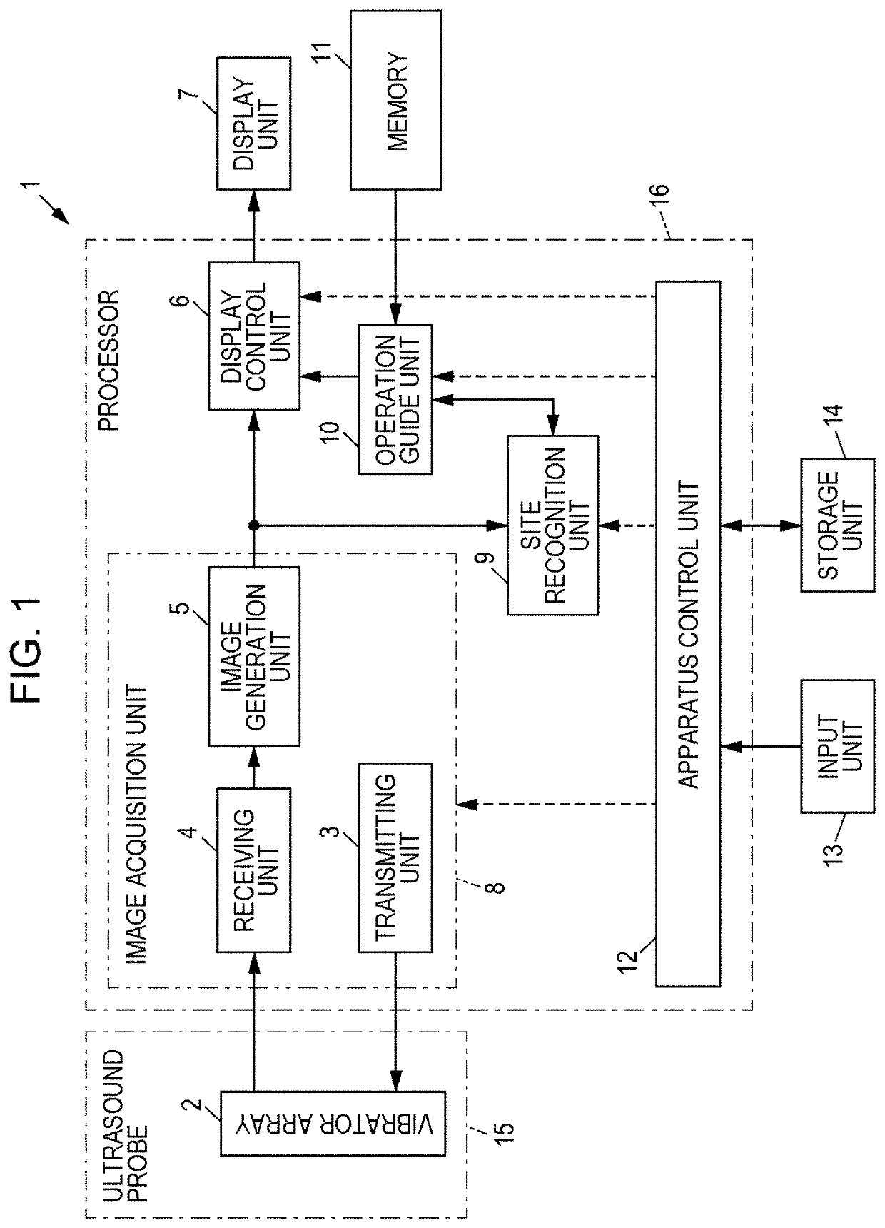
[0054]FIG. 1 illustrates a configuration of an ultrasound diagnostic apparatus 1 according to Embodiment 1 of the present invention. As illustrated in FIG. 1, the ultrasound diagnostic apparatus 1 includes a vibrator array 2, and the vibrator array 2 is connected to a transmitting unit 3 and a receiving unit 4. The receiving unit 4 is sequentially connected to an image generation unit 5, a display control unit 6, and a display unit 7. The transmitting unit 3, the receiving unit 4, and the image generation unit 5 constitute an image acquisition unit 8. The image generation unit 5 is further connected to a site recognition unit 9, and the site recognition unit 9 is connected to an operation guide unit 10. The site recognition unit 9 and the operation guide unit 10 are connected so as to enable two-way exchange of information. The operation guide unit 10 is further connected to a memory 11 and the display control unit 6.

[0055]Further, the display control unit 6, the image acquisition u...

embodiment 2

[0112]Embodiment 1 provides an example in which the common bile duct is detected as a specific example of the target site M. The present invention is also applicable to the detection of any other site. In Embodiment 2, the operation of the ultrasound diagnostic apparatus 1 for detecting the appendix as a specific example of the target site M different from the common bile duct will be introduced with reference to FIG. 10 to FIG. 13. It is assumed here that the memory 11 stores a short-axis view of the ascending colon as a peripheral site A effective to detect the appendix, a long-axis view of the cecum as a peripheral site B, and a long-axis view of the ileum as a peripheral site C, and further stores a detection order such that the peripheral sites are detected in the order of the peripheral site A, the peripheral site B, and the peripheral site C.

[0113]The short-axis view of the ascending colon represents a transverse cross-sectional image of the cross section of the ascending col...

embodiment 3

[0127]In the neck of the human body, seven cervical vertebrae, including the first cervical vertebra to the seventh cervical vertebra, exist from the head side, and the spinal cord runs through the first cervical vertebra to the seventh cervical vertebra. Further, a plurality of nerves extend from the spinal cord through each of the seven cervical vertebrae. Nerve roots of the nerves are generally observed using an ultrasound diagnostic apparatus during the diagnosis of a disease or the like, such as in the practice of so-called nerve blocks and the like. Among the nerve roots of the first cervical vertebra to the seventh cervical vertebra, the nerve roots of the fifth cervical vertebra to the seventh cervical vertebra run in parallel in such a manner as to be adjacent to each other, and thus it is generally difficult for a less experienced user to identify the nerve roots of the fifth cervical vertebra to the seventh cervical vertebra by observing an ultrasound image.

[0128]Furtherm...


PUM


Abstract

An ultrasound diagnostic apparatus 1 includes an ultrasound probe 15, an image acquisition unit 8 that transmits an ultrasound beam from the ultrasound probe 15 to a subject to acquire an ultrasound image, a site recognition unit 9 that performs image analysis on the ultrasound image acquired by the image acquisition unit 8 to recognize an imaged site of the subject, a memory 11 that stores at least one peripheral site effective to detect a target site, and an operation guide unit 10 that, during detection of the target site, guides a user to operate the ultrasound probe 15 so as to detect the at least one peripheral site stored in the memory 11 and guides the user to operate the ultrasound probe 15 so as to detect the target site on the basis of a recognition result obtained by the site recognition unit 9.

Description

CROSS-REFERENCE TO RELATED APPLICATIONS[0001]This application is a Continuation of PCT International Application No. PCT / JP2018 / 042652 filed on Nov. 19, 2018, which claims priority under 35 U.S.C. § 119(a) to Japanese Patent Application No. 2018-015382 filed on Jan. 31, 2018 and Japanese Patent Application No. 2018-103436 filed on May 30, 2018. Each of the above applications is hereby expressly incorporated by reference, in its entirety, into the present application.BACKGROUND OF THE INVENTION1. Field of the Invention[0002]The present invention relates to an ultrasound diagnostic apparatus, a method for controlling the ultrasound diagnostic apparatus, and a processor for the ultrasound diagnostic apparatus and more specifically to an ultrasound diagnostic apparatus for guiding a user to operate an ultrasound probe, a method for controlling the ultrasound diagnostic apparatus, and a processor for the ultrasound diagnostic apparatus.2. Description of the Related Art[0003]Ultrasound di...

Claims


Application Information

Patent Timeline
Patent Type & Authority Applications(United States)
IPC IPC(8): A61B8/08A61B8/00G06T7/00
CPCA61B8/42G06T2207/30028A61B8/467G06T2207/30012G06T7/0014A61B8/463G06T2207/30101A61B8/085G06T2207/10132A61B8/565A61B8/54A61B8/4245G16H40/63A61B8/465G16H30/20G16H30/40G16H50/20A61B8/5223
Inventor MATSUMOTO, TSUYOSHIINOUE, TOMOKIEBATA, TETSUROU
Owner FUJIFILM CORP
Why Eureka
Try Eureka