
Plating compositions for electrolytic copper deposition, its use and a method for electrolytically depositing a copper or copper alloy layer onto at least one surface of a substrate

Active Publication Date: 2020-11-05
ATOTECH DEUT GMBH
View PDF0 Cites 2 Cited by
  • Summary
  • Abstract
  • Description
  • Claims
  • Application Information

AI Technical Summary

Benefits of technology

This patent describes a new method for coating surfaces with copper using electrolytic deposition. The method has several advantages such as producing smooth copper layers that adhere well to the surface, and the plating composition can handle high current densities, allowing for uniform layer formation. These technical effects make the method easier to use and more efficient for producing copper coatings.

Problems solved by technology

Such dyes have certain disadvantages, in particular when used in large quantities.
For example, if spilled they are difficult to remove and they are very expensive adding significantly to the cost of the copper plating process.
Further, many commercial phenazinium compounds still contain certain amounts of the used starting materials which are often toxic such as aniline and nitrobenzene.
Additionally, some copper electrolytes described above do not allow the use of high current densities as is desired for electroplating.
For substrates having complex shapes and / or structured surfaces known methods and plating solutions are not sufficient.
It is not possible to produce decorative bright and conformal surfaces that have no undesirable effects such as over-levelled structures, hydrodynamic defects, pittings and nodules.
Furthermore, when using known solutions, it is not possible to achieve good levelling performance without compromising the bright appearance of the surface layer and using higher current densities.
Especially small structures with protrusions, different deep recesses or increments show undesired different copper growth resulting in uneven surface appearance wherein the copper layer will not smoothly follow the shape of the structures.
Furthermore, it is often not possible to achieve a reproducible quality of particularly bright, i.e. mirror-polished, as well as well levelled and ductile copper deposits.
Another shortcoming of the prior art is that the roughness of copper layers formed from copper electrolytes known in the art is not only too high for many applications but also quickly increases over the lifetime of the bath.
However, the replenishment of such compounds has to be arduously adapted to this need as not all compounds are consumed in the ratio and an inaccurate addition of component may result in further undesired effects.

Method used


Image

  • Plating compositions for electrolytic copper deposition, its use and a method for electrolytically depositing a copper or copper alloy layer onto at least one surface of a substrate
  • Plating compositions for electrolytic copper deposition, its use and a method for electrolytically depositing a copper or copper alloy layer onto at least one surface of a substrate
  • Plating compositions for electrolytic copper deposition, its use and a method for electrolytically depositing a copper or copper alloy layer onto at least one surface of a substrate

Examples


##ventive example 1

Inventive Example 1

[0200]A plating composition comprising the following components was prepared by dissolving the named components in water:

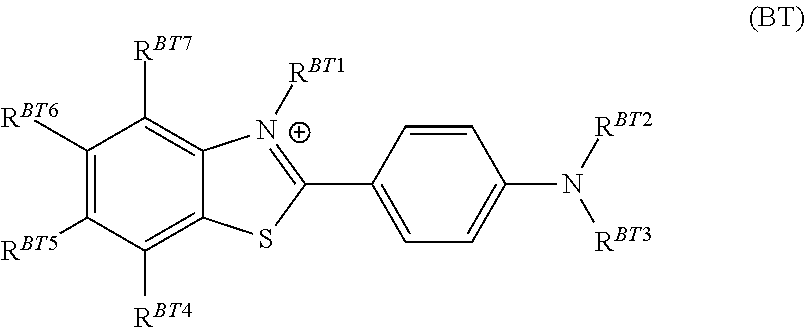
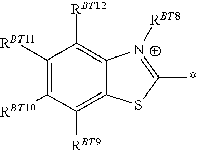
CuSO4 × 5 H2O220.0g / LSulfuric acid (96% per weight)70.0g / LNaCl160mg / Liron ions100mg / Lpolymeric safranine3mg / Lbis-(ω-sulfopropyl)-disulfide30mg / LTetronic ® 304200mg / Lthioflavin T6mg / L

[0201]The plating conditions were identical to those described in Comparative Example 1. The resulting roughness SA was 46.6 nm (at 2 ASD) corresponding to a levelling effect of 52% compared to the scratched virgin substrate. The copper layers were glossy over the whole substrate and had a mirror-polished appearance. They additionally adhered well to the underlying substrate and were ductile as desired in the art.

Inventive Example 2: Preferred Embodiment

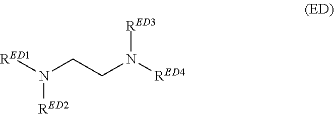
[0202]The plating composition of Inventive Example 1 was used but instead of Tetronic® 304, an ethanediamine derivative was used in the same concentration as Tetronic® 304 in Inventive Example 1. At least one of RED1 ...

##ventive example 3

Inventive Example 3

[0206]A plating composition comprising the following components was prepared by dissolving the named components in water:

CuSO4 × 5 H2O220.0g / LSulfuric acid (96% per weight)70.0g / LNaCl160mg / Liron ions100mg / Lpolymeric safranine3mg / Lbis-(ω-sulfopropyl)-disulfide30mg / Lthioflavin T2mg / Lethanediamine derivative of200mg / LInventive Example 2

[0207]The plating composition was used in a Hull cell to plate on substrates with the following parameters: current per panel: 2 A, temperature: 25° C., time: 10 min, air injection using phosphorus-containing soluble copper anodes. Then, the roughness was measured and compared to the examples below. Between the evaluation of the plating solution by plating with above parameters on scratched virgin substrates, the plating composition was aged by passing a defined charge (see table) through the composition.

TABLE 2Inventive Example 3.currentPlatingIncrease ofdensitysolutionroughness com-[A / dm2]agepared to 1.3 Ah / L21.3 Ah / Lreference value2...


PUM

PropertyMeasurementUnit
Fractionaaaaaaaaaa
Fractionaaaaaaaaaa
Fractionaaaaaaaaaa

Abstract

The present invention relates to a plating composition for electrolytic copper deposition, comprising copper ions, halide ions and at least one acid, at least one benzothiazole compound, at least one phenazine dye and at least one ethanediamine derivative. The present invention further concerns the use of above plating composition and a method for electrolytically depositing a copper or copper alloy layer onto at least one surface of a substrate.

Description

FIELD OF THE INVENTION[0001]The present invention concerns plating compositions for electrolytic copper deposition, their use and a method for electrolytically depositing a copper or copper alloy layer onto at least one surface of a substrate.BACKGROUND OF THE INVENTION[0002]Various methods and deposition solutions for copper plating are used to produce decorative bright and levelled surfaces, large surfaces for instance, on metals or plastic materials. Among others, they are used to form ductile layers, for example in the field of decorative coatings for sanitary or automotive equipment where there is a need for intermediate copper layers for subsequent deposition of different metal layers e.g. for corrosion protection and / or decorative layers.[0003]A homogeneous and bright appearance is especially required for final metal layers on the surface of the substrate. The homogeneity of the appearance can be easily achieved on substrates which have no complex shape because the current de...

Claims


Application Information

Patent Timeline
IPC IPC(8): C25D3/38C09B17/02
CPCC09B17/02C25D3/38
Inventor WACHTER, PHILIPPPFIRRMANN, CHRISTINAKRETSCHMER, STEFAN
Owner ATOTECH DEUT GMBH
Learn More