Sealed Disposable Concrete Vibrator

a concrete and sealing technology, applied in the field of concrete vibrators, can solve the problems of high stress load, low production efficiency, and inability to flow well, and achieve the effect of reducing the cost and ultimate sale price of the vibrator, simple and rugged design, and machining steps necessary to create the vibrator

Inactive Publication Date: 2020-11-05
MULTIQUIP
View PDF0 Cites 4 Cited by
  • Summary
  • Abstract
  • Description
  • Claims
  • Application Information

AI Technical Summary

Benefits of technology

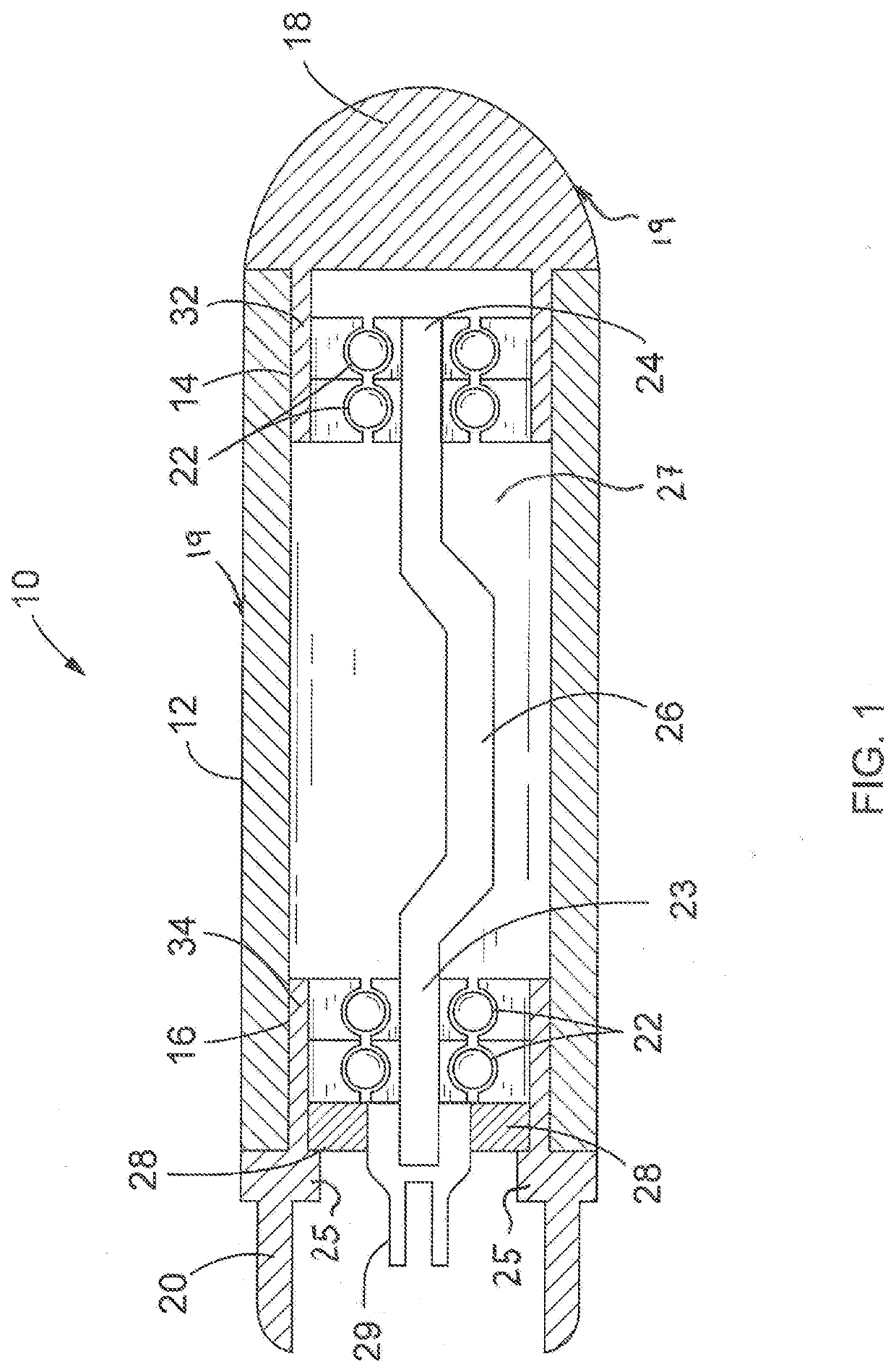
[0010]The rotating eccentric shaft may be fabricated from manufactured steel, forged or cast or powdered metal materials or a composite, depending upon model design. The main housing and tip cover are typically hardened to extend life. In a preferred embodiment, the main housing and the outer surface of the tip cover are encased in plastic or a rubber-like material so that the concrete vibrating assembly may be used with plastic coating rebar applications without damaging or stripping away the plastic coating on the rebar.
[0011]A flexible drive shaft adaptor is accommodated within the adaptor housing and is attached to the driven end of the rotating eccentric shaft. The adaptor housing and design may vary depending upon the flexible drive shaft interface intended to be used with a particular concrete vibrator assembly. Similarly, the design features of the flexible drive shaft adaptor may depend on the design of the eccentric drive shaft to which the adaptor is intended to be connected. In between the adaptor housing and the proximal end sealed bearings is an oil seal of suitable dimensions and materials to seal the concrete vibrator assembly to prevent contamination of the interior of the vibrator during operation and when immersed in concrete, and to prevent leakage of lubricant out of the main housing.
[0013]As can be seen in the preferred embodiment, the machining steps necessary to create a vibrator according to the invention are minimal, thus greatly reducing the cost and ultimate sale price of the vibrator. It has also been found that a vibrator of the present invention, though relatively simple and rugged in design, will have as long a service life as the much more expensive, disassembleable, concrete vibrators known in the prior art and that cost savings achieved through this design, when taken together with the avoided cost of replacement bearings and labor to rebuild a more expensive concrete vibrator, more than economically justify the use of the sealed disposable concrete vibrator assembly of the present invention.

Problems solved by technology

Unfortunately, relatively dry, low slump concrete does not flow well and the concrete must be consolidated, that is to say the air pockets must be removed from the concrete to ensure structural integrity of the vertical columns.
Obviously, the bearings supporting the rotating eccentric shaft are subjected to continuously variable and high stress loads.
This prior art assumption, that a key feature of an immersible concrete vibrator is the ability to disassemble the vibrator to facilitate the replacement of the bearings, is the root cause of a number of problems in the prior art.
This results in a number of expensive machining processes to provide for a threaded screw or breach lock mechanism at each end of the vibrating canister, along with the attendant and appropriate oil seals, to prevent contamination of the interior of the vibrator by concrete when it is immersed in newly poured concrete and in operation.
If the operator fails to turn off the concrete vibrator when it is not immersed in concrete, the concrete vibrator will rapidly overheat the bearing surfaces to the point where they require replacement.
Another problem is that even though the prior art concrete vibrator is designed to be disassembled so that bearings may be replaced as routine maintenance requires, the routine maintenance is often postponed or not performed at all, usually because of cost, or problems locating proper sized bearing assemblies, or absence of skilled mechanics trained in the proper installation of new bearing assemblies.
Since the extra machining steps involved in producing a concrete vibrator that can be disassembled are significant, replacement costs are accordingly expensive.

Method used


Image

  • Sealed Disposable Concrete Vibrator
  • Sealed Disposable Concrete Vibrator

Examples


Embodiment Construction

[0017]While the presently disclosed inventive concepts are susceptible to various modifications and alternative constructions, certain illustrated embodiments thereof have been shown in the drawings and will be described below in detail. It should be understood, however, that there is no intention to limit the inventive concepts to the specific form disclosed, but, on the contrary, the presently disclosed and claimed inventive concepts are to cover all modifications, alternative constructions, and equivalents falling within the spirit and scope of the inventive concepts as defined in the claims.

[0018]FIG. 1 shows a sectional representation of a side view of our new sealed disposable concrete vibrator 10. Provided is a main housing 12, which, in the preferred embodiment, is of hollow cylindrical form open at both proximal and distal ends. Main housing 12 may be formed either from a casting or from a fabricated metal tube and may be provided with a distal end machined inner surface 14...


PUM


Abstract

A sealed disposable concrete vibrator assembly includes a hollow cylindrical main housing enclosing a shaft having an eccentric mid portion sized to rotate therewithin. Sealed bearings supporting the shaft are encased within an adaptor housing and a tip cover attached concentrically to proximal and distal ends, respectively, of the main housing. Outer surfaces of the adaptor housing and tip cover protrude into the main housing for frictional engagement therewith, while inner surfaces thereof provide channels to encase the bearings. An oil seal compressed against a flange integral to the adaptor housing prevents intrusion of contaminants. A circumvolving adaptor is coupled through the oil seal to the driven end of the shaft. The assembly may be hermetically sealed by permanent attachment of the adaptor housing and tip assembly to the main housing.

Description

TECHNICAL FIELD[0001]The presently disclosed technology relates to concrete vibrators intended for immersion in newly poured, low slump concrete of the type commonly used for construction of concrete columns, where the vibrators are used to eliminate air pockets in newly poured concrete by consolidating the newly poured concrete.BACKGROUND[0002]Vertical columns for bridges and multi-story buildings are typically made of concrete, reinforced by rebar, which is often coated with some sort of plastic and fabricated using very dense, somewhat dry, low flowability, low slump concrete. This is done to achieve the maximum compressive value reasonably available to attain the highest compressive strength columns that may be required or can be achieved. Typically, these columns are poured in place, and are heavily reinforced with rebar, which is often wired together to increase the shear strength of the vertical column. The rebar itself, often in order to extend its useful life, is coated in ...

Claims


Application Information

Patent Timeline
Patent Type & Authority Applications(United States)
IPC IPC(8): E04G21/08B01F11/00B06B1/16
CPCB01F11/0097E04G21/08B06B1/16B01F2215/0047B01F31/70B01F2101/28
Inventor CLEMENTS, TYLER N.GILBERT, CHRISTOPHER G.
Owner MULTIQUIP
Why Eureka
Try Eureka