
Structural health monitoring for an industrial structure

a technology for industrial structures and health monitoring, applied in the field of metals, can solve the problems of known approaches with limitations, fluid flowing through a pipe naturally causing noise in a privileged direction, and the solution described in wo 2015/082292 has limitations, so as to reduce the intensity of computing time, improve the uniform spatial distribution of noise sources, and improve the effect of quality

Active Publication Date: 2020-11-12
COMMISSARIAT A LENERGIE ATOMIQUE ET AUX ENERGIES ALTERNATIVES
View PDF6 Cites 4 Cited by
  • Summary
  • Abstract
  • Description
  • Claims
  • Application Information

AI Technical Summary

Benefits of technology

The invention is based on a method called passive inverse filter (PIF) that improves the quality of signals obtained from a set of sensors. This method allows for better tomography imaging and the use of more advanced algorithms. By using PIF, the uniformity of noise distribution is increased and non-equipartition of noise is compensated for, making it applicable to a wider range of industrial configurations. Additionally, the method is faster and allows for high-rate delivery of tomographs.

Problems solved by technology

One concrete technical problem for example consists in detecting and determining the size of a corroded region in an airplane fuselage.
A general technical problem is that of finding an acceptable compromise between the nature of the sensors to be integrated, the number of these sensors (cost, bulk, weight, etc.) and the quality of the information collectable by these sensors.
The known approaches have limitations.
Nevertheless, despite its advantages, the solution described in WO 2015 / 082292 has limitations.
In the same way, a fluid flowing through a pipe naturally induces noise in a privileged direction.
This type of tomography can only characterize a limited class of defects (i.e. weakly diffracting structural defects).
The defect morphologies that can be characterized are limited.
Despite its advantageousness, the approach adopted in this document has limitations.

Method used


Image

  • Structural health monitoring for an industrial structure
  • Structural health monitoring for an industrial structure
  • Structural health monitoring for an industrial structure

Examples


Embodiment Construction

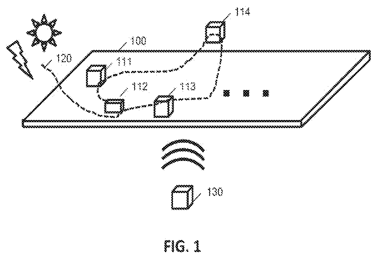
[0022]A “diffuse elastic field” designates waves that propagate through a continuous medium, a solid medium for example. Liquid and gaseous media are generally excluded from the scope of the invention. The term “diffuse” indeed underlines that propagation effects occur in the medium (e.g. refraction, diffraction, reverberation, etc.). The types of media in question are therefore those addressed in the technical field of structural health monitoring in industrial environments (e.g. airplane-wing profiles, beams, tubes or pipes, sheets of steel or slabs of concrete, etc.).

[0023]The diffuse elastic field is due to “ambient noise”. This noise may be of natural origin (turbulence around an airplane-wing profile). In certain embodiments, in addition to ambient noise, one or more sources of “active” or “artificial” noise may advantageously be used.

[0024]The Green's function (of a medium or of a structure or of a space) designates the solution of a linear differential equation (or partial d...


PUM


Abstract

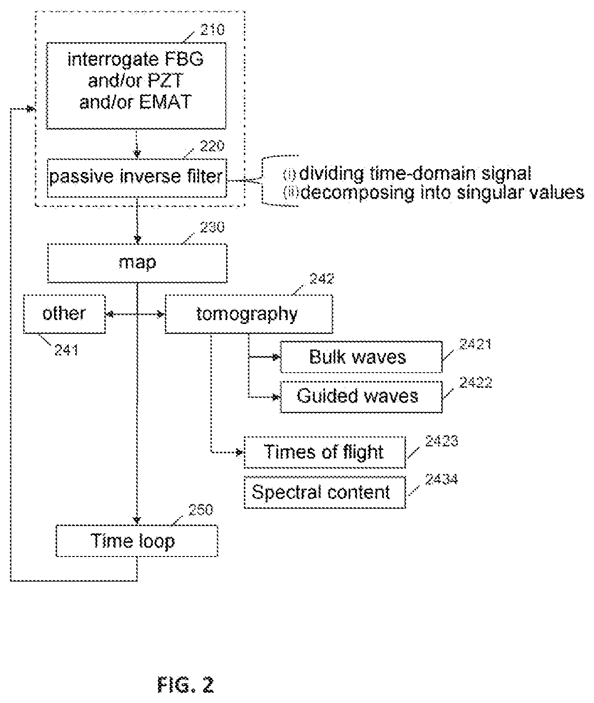
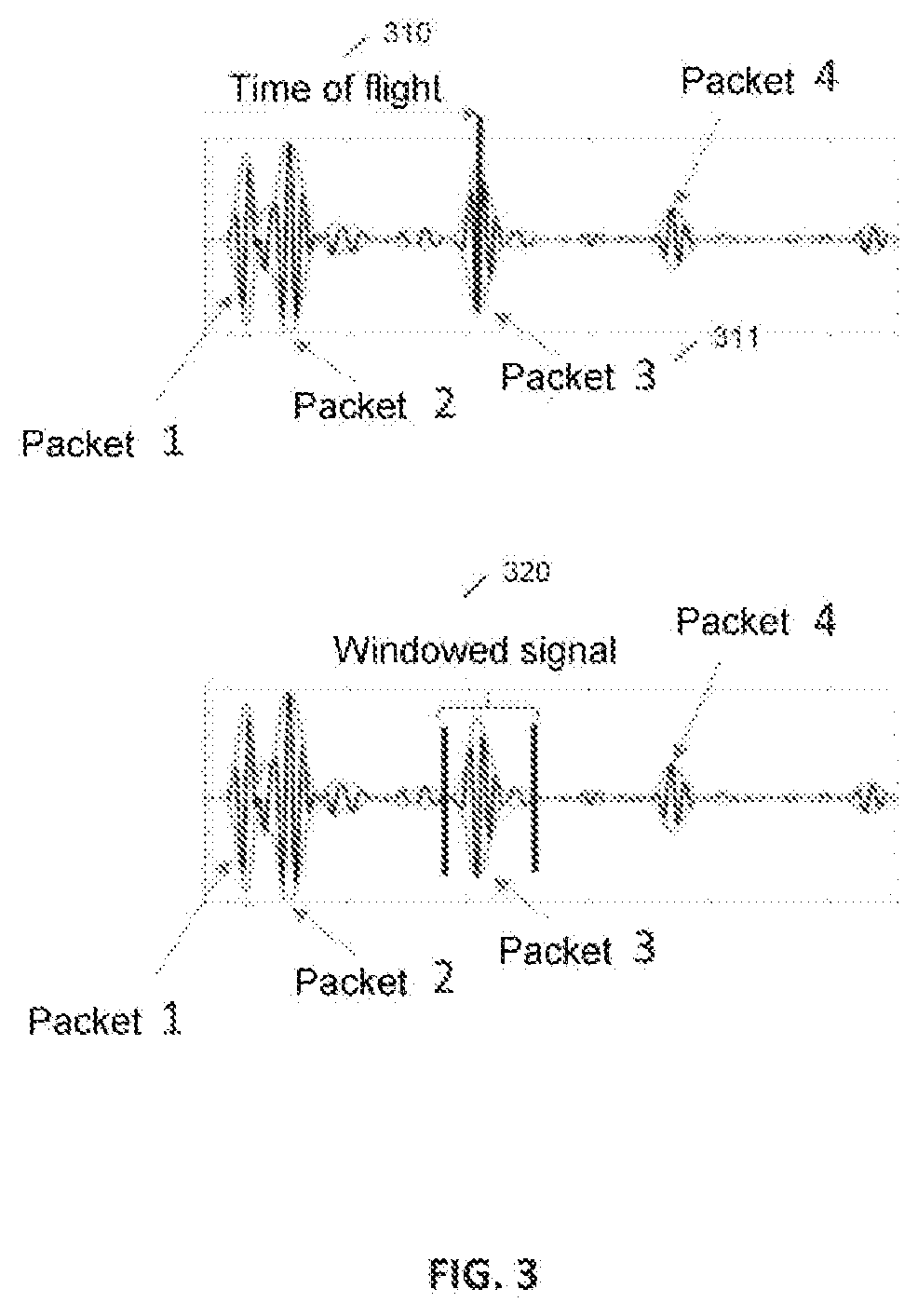
Methods and systems for analyzing an industrial structure are provided. With a plurality of sensors (e.g. FBGs and / or piezoelectric transducers and / or electromagnetic acoustic transducers) deployed in, on or in proximity to the structure, sensors are interrogated and a function representative of the impulse response of the structure is determined by passive inverse filter. Subsequently, a map of the propagation of the elastic waves through the structure is determined via various modalities, and in particular by tomography (of bulk or guided waves, by analysis of time of flight or of the complete signal). Embodiments especially relate to the management of the number and position of the sensors, to the use of artificial noise sources, and to automatically controlling the sensors and / or noise sources to monitor the health of the structure, or even to view the dynamic behavior of the structure.

Description

FIELD OF THE INVENTION[0001]The invention relates to the field of metrology in general, and in particular to the field of monitoring the health of industrial structures, i.e. structural health monitoring or SHM.PRIOR ART[0002]The integrity of structures (works of art, airplane wings or a pipeline, for example) over their life is generally monitored during maintenance operations, with human inspection and intervention. One concrete technical problem for example consists in detecting and determining the size of a corroded region in an airplane fuselage.[0003]For these inspections of integrity, non-destructive testing (NDT) methods employing “conventional” techniques (ultrasound, electromagnetic techniques, etc.) are generally used. Research aiming to integrate sensors into a structure at key points of the structure has been underway for a number of years, with a view to automating the measurements (which are for example taken at regular intervals, these intervals generally being close...

Claims


Application Information

Patent Timeline
Patent Type & Authority Applications(United States)
IPC IPC(8): G01M5/00G06T7/00G06F17/15
CPCG06F17/156G06T2207/10072G06T7/0002G01M5/0066G01M5/0091G01N29/043G01N29/0609G01N29/0654G01N29/0672G01N29/14G01N29/2412G01N29/2418G01N29/2437G01N29/245G01N29/2475G01N29/4454G01N29/46G01N29/52G01N2291/0231G01N2291/0289G01N2291/2634G01N2291/2694G01N2291/02827
Inventor CHAPUIS, BASTIENDRUET, TOM
Owner COMMISSARIAT A LENERGIE ATOMIQUE ET AUX ENERGIES ALTERNATIVES
Learn More