
Two-speed transmission system integrated with inner rotor hub motor and electric vehicle using same

Active Publication Date: 2020-12-10
JILIN UNIV
View PDF0 Cites 10 Cited by
  • Summary
  • Abstract
  • Description
  • Claims
  • Application Information

AI Technical Summary

Benefits of technology

This invention has two-speed transmission system integrated with an inner rotor hub motor that has a simple structure and compact arrangement. It can be easily mounted in the wheels and reduces the axial size of the entire transmission system. Additionally, it has two electromagnetic brakes that share a friction disk, reducing the number of parts and components. Overall, this invention has a highly-integrated structure.

Problems solved by technology

Though automobiles provide a lot of conveniences, they also lead to numerous negative effects.
For example, a large number of non-renewable resources such as oil and natural gas are consumed, which results in the generation of a considerable number of toxic and harmful gases such as carbon monoxide and nitrogen oxides and greenhouse gases such as carbon dioxide together with a lot of noise, causing immeasurable harm to our living environment.
Currently, the energy crisis and the environmental problems are worsening worldwide, and car ownership is still increasing year by year, which further aggravates the above problems.
For the vehicles driven by the concentrated motor, the power is transmitted to the driving wheels generally through a transmission, a differential mechanism, a universal driving device, etc., which leads to complicated structure and low transmission efficiency.
In addition, the wheels fail to be independently controlled.
Therefore, the conventional in-wheel motor-driving system, whether the wheel-side driving or hub-motor driving, only has a constant speed ratio, failing to reasonably adjust the speed ratio according to actual driving conditions to balance the requirements of the electrical vehicles driven by in-wheel motors for dynamics performance and driving economics.

Method used


Image

  • Two-speed transmission system integrated with inner rotor hub motor and electric vehicle using same
  • Two-speed transmission system integrated with inner rotor hub motor and electric vehicle using same
  • Two-speed transmission system integrated with inner rotor hub motor and electric vehicle using same

Examples


Embodiment Construction

[0068]The present invention will be further described in detail below with reference to the accompanying drawings to enable those skilled in the art to fully understand the technical solutions of the invention.

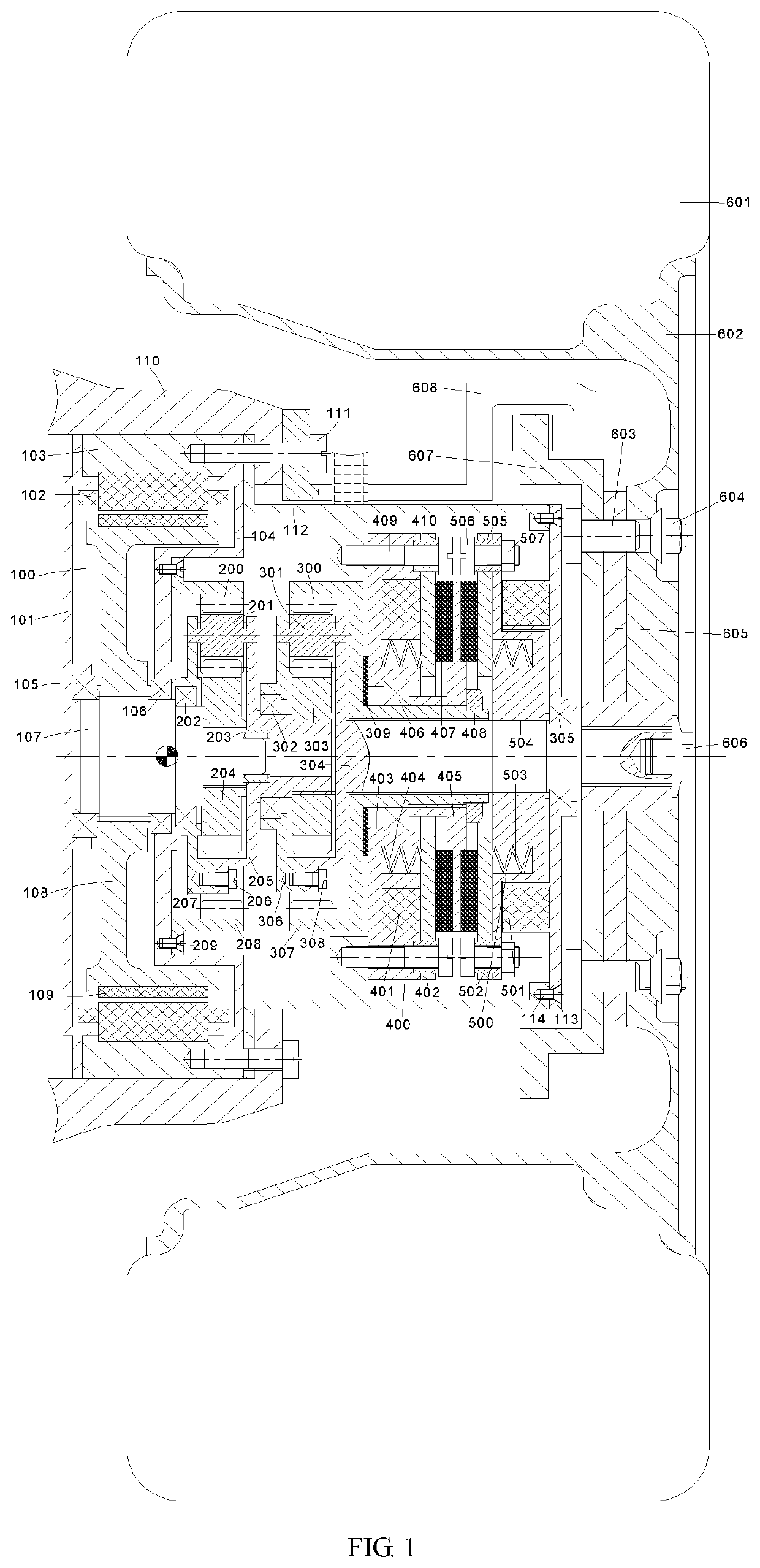
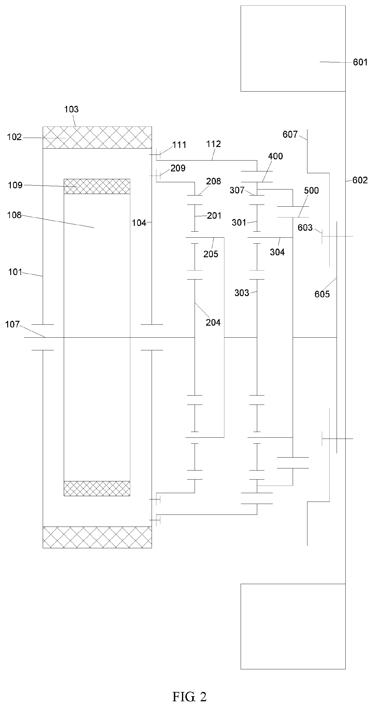
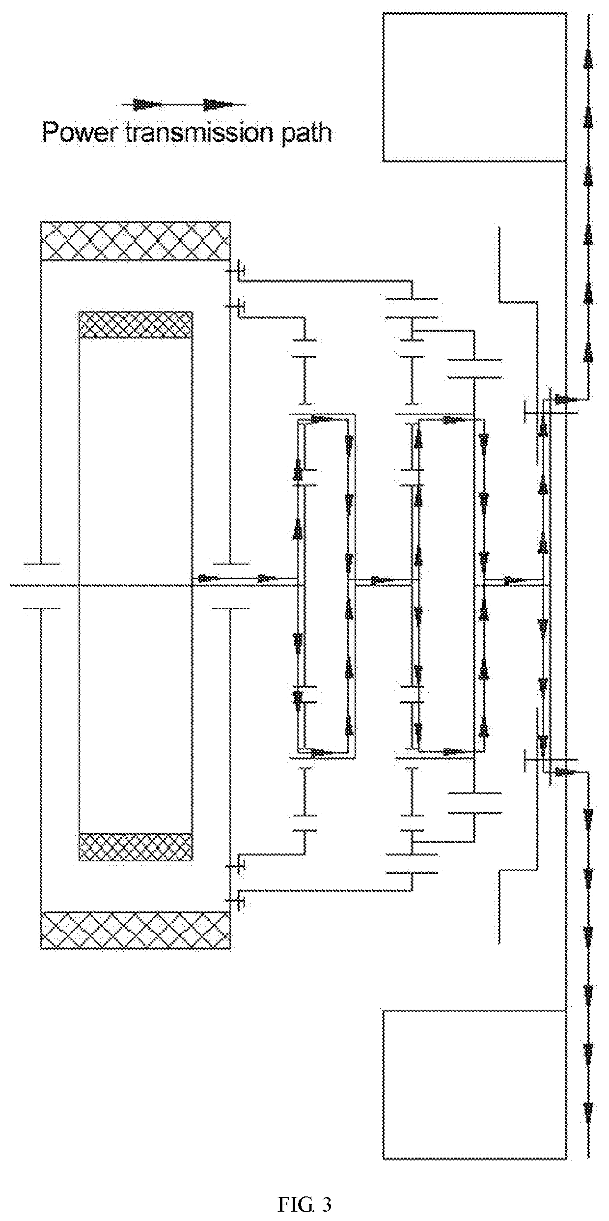
[0069]This invention provides a two-speed transmission system integrated with an inner rotor hub motor as shown in FIG. 1, which includes an inner rotor hub motor as a power source, two planetary gear trains for speed reduction and torque improvement and two electromagnetic brakes for gear shifting. Thus, the transmission can be switched among various gears to adapt to actual driving conditions of the electric vehicles. In addition, due to the rapid response, the gear shifting process is completed in a extremely short time, achieving better dynamics and economics and improving overall performances of the electric vehicles. The two-speed transmission system enables not only the gear shifting, but also the parking braking.

[0070]The two-speed transmission system integrated with t...


PUM


Abstract

A two-speed transmission system integrated with an inner rotor hub motor, including an inner rotor hub motor, a steering knuckle, a fastening screw, a first transmission casing, a second transmission casing, a screw, a first planetary gear train, a second planetary gear train, a first electromagnetic brake, a second electromagnetic brake, a tire, a wheel rim, a rim bolt, a rim nut, a wheel hub, a shaft end bolt, a brake disc and a brake caliper. This invention also provides an electric vehicle, which balances the requirements for dynamics performance and driving economics and achieves better overall performances. The two-speed transmission system of this invention realizes gear shifting and long-term no-power parking braking.

Description

CROSS-REFERENCE TO RELATED APPLICATIONS[0001]This application claims the benefit of priority from Chinese Patent Application No. 201910487833.8, filed on Jun. 5, 2019. The content of the aforementioned application, including any intervening amendments thereto, is incorporated herein by reference in its entirety.TECHNICAL FIELD[0002]The application relates to electric vehicles, and more particularly to a two-speed transmission system integrated with an inner rotor hub motor and an electric vehicle using the same.BACKGROUND OF THE INVENTION[0003]The rapid development of the automotive industry has greatly changed our living style and improved our living quality. Though automobiles provide a lot of conveniences, they also lead to numerous negative effects. For example, a large number of non-renewable resources such as oil and natural gas are consumed, which results in the generation of a considerable number of toxic and harmful gases such as carbon monoxide and nitrogen oxides and gree...

Claims


Application Information

Patent Timeline
IPC IPC(8): B60K17/04B60K7/00F16H3/64F16H57/033F16H61/02F16H61/686H02K7/00H02K7/116H02K7/102
CPCH02K7/006F16H61/686F16H2200/2035B60K2007/0092B62D7/18B60K7/0007F16H57/033B60K17/046H02K7/116H02K7/1025F16H2200/0034F16H2200/0021F16H2057/02043F16H61/0204F16H2057/02034F16H2200/2007B60T1/065F16H3/64B60L7/00H02K1/278H02K7/1846H02K5/1732B60Y2400/423B60K17/02B60K17/08B60K2007/0038B60B27/0052B60B35/125F16D2121/20F16H2063/3046F16H3/66
Inventor WANG, JUNNIANWANG, KAIGUO, DACHANGZHANG, CHUNLINLUO, RUIZHANG, ZHENHAOGAO, JIULONGNI, JIANTU
Owner JILIN UNIV
Learn More