
Hybrid Finite Element and Artificial Neural Network Method and System for Safety Optimization of Vehicles

Inactive Publication Date: 2020-12-17
VARON WEINRYB ABRAHAM
View PDF0 Cites 4 Cited by
  • Summary
  • Abstract
  • Description
  • Claims
  • Application Information

AI Technical Summary

Benefits of technology

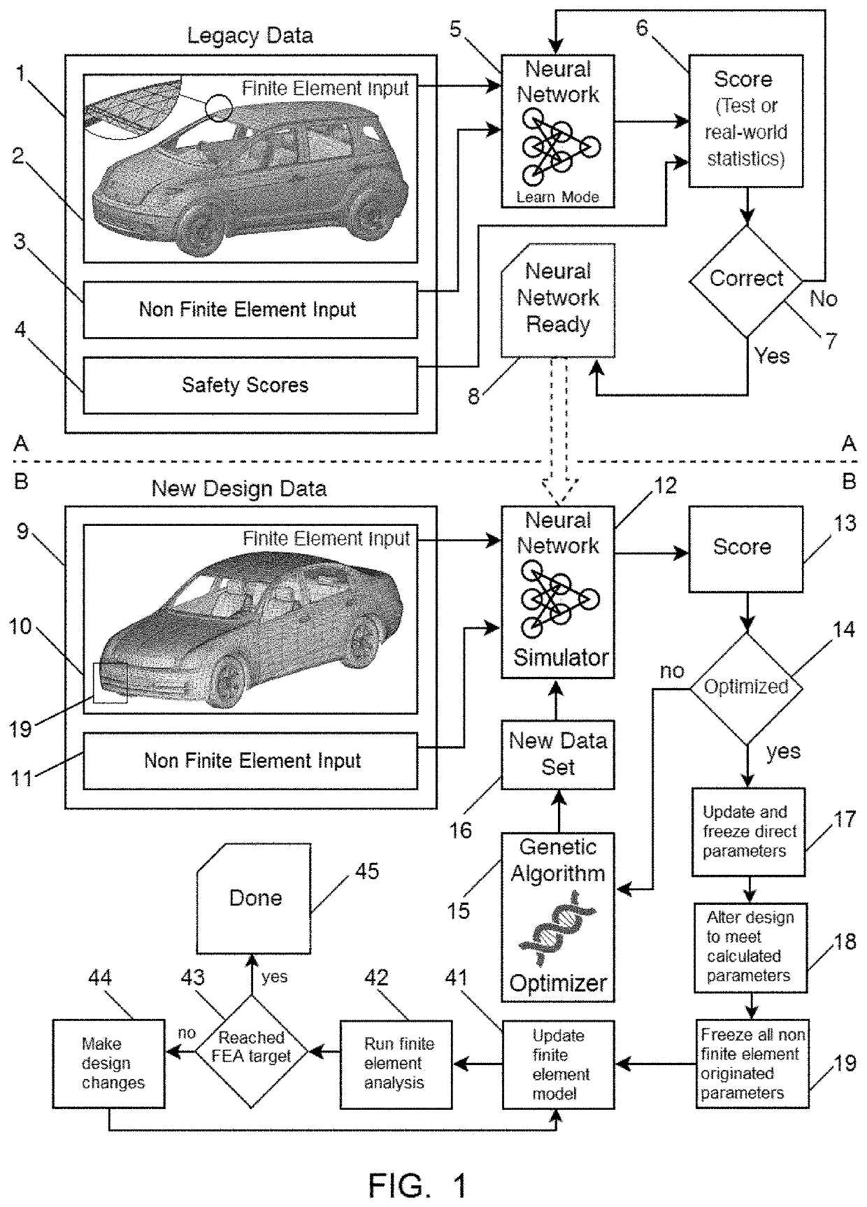
The invention is a computer-based method for optimizing the design of vehicles to improve safety. The method involves collecting data on existing cars and their safety parameters, creating an artificial neural network to learn how to reach desired safety goals, and using the neural network as a simulator to find optimal values for new car designs. The method also involves iteratively freezing and updating the design based on the input of the neural network and analyzed data. The invention can reveal correlations between design data and safety, and can also learn from real-world crash statistics data to improve safety. The method can be performed using a genetic algorithm or a gradient descent method. The invention can also involve multiple optimization sessions to provide optimized design recommendations for the next design phase.

Problems solved by technology

This is a very late stage of the development cycle, therefore it is not feasible in terms of cost and time-to-market to redesign, remanufacture and retest a car in order to optimize its safety, unless the tests results are unacceptable.
Another limitation of such tests is that the safety scores are not based on any real-world data, but only on the test itself.
In addition, the measuring equipment and methods have their own inaccuracies.
Yet another limitation of a crash test is that it does not and cannot provide safety data relating to other cars that might be involved in the real-world crash situation of the tested car.
However, such simulation is extremely complicated and has many limitations.
A finite element analysis of a car crash is one of the most challenging application of structural finite element analysis.
Such highly dynamic and nonlinear simulation needs to be applied to a very complex 3D model of a car assembly, resulting in a very large finite element model.
Other complexity aspects of such model may involve the obvious need to use and combine various finite element types such as volume elements, surface elements, line elements, scalar elements and special elements such as rigid body elements, as well as the need to use complex materials and their related failure criteria.
The boundary conditions and loads definitions of such model are also very complicated.
It is difficult to define the related frequency-dependent damping coefficients, which are critical to the dynamic behavior of the model during a transient dynamic analysis.
As a result, such a model is both very large and very complicated.
Yet, it is still a must to include some assumptions and simplifications to such model, which affect its accuracy.
Indeed, existing simulation tools are limited in functionality and in use.
They require a massive expert's work during the preprocessing phase, and long runtime during the solver's phase.
The results of such significant investment are limited.
The accumulative inaccuracies of such simulation might be huge.
In addition, and similar to limitations of crash tests, such existing simulation methods do not and cannot predict how the simulated design affects the safety of surrounding cars and their passengers during crash situations, in which the simulated car and such surrounding cars are involved.
However, there are too many limitations, assumptions and inaccuracies, and this method is less useful and less accurate comparing to the finite element method.
Yet, the above-mentioned main limitations of functionality and accuracy still very much exist for these specific modules as well.
However, and just like with the crash simulation software limitations, there are both accuracy and functionality limitations to physical crash tests, that cannot be eliminated.
Another common limitation of both existing crash tests and existing methods of crash simulation is the inability of such methods to reveal dormant correlations between a car's characteristics and the related impact of such characteristics on the human body during crash situations.

Method used


Image

  • Hybrid Finite Element and Artificial Neural Network Method and System for Safety Optimization of Vehicles
  • Hybrid Finite Element and Artificial Neural Network Method and System for Safety Optimization of Vehicles
  • Hybrid Finite Element and Artificial Neural Network Method and System for Safety Optimization of Vehicles

Examples


example 1

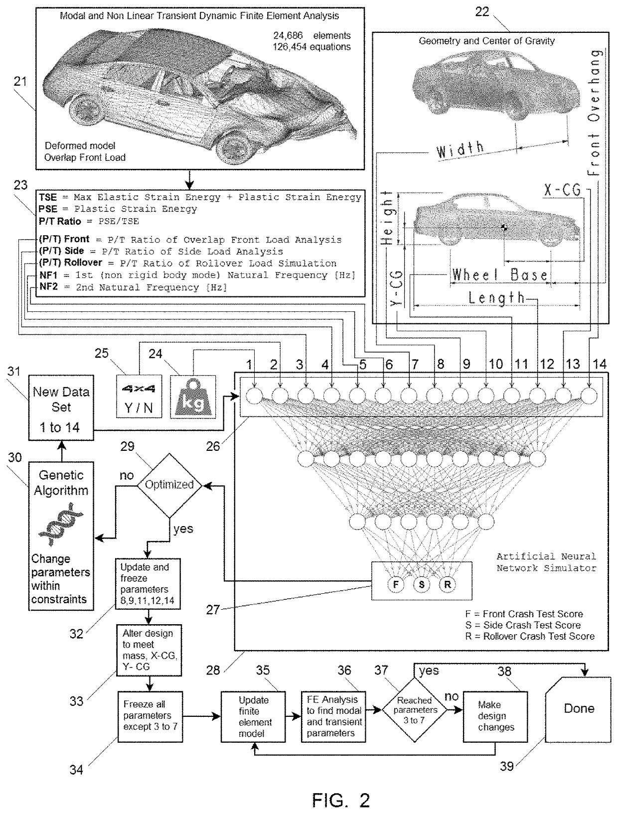
[0091]FIG. 2 shows the first example. The finite element part in this example includes both a modal analysis and 3 nonlinear transient dynamic finite element analyses. As said, the method of this invention enables significant simplification of the finite element solution, due to the qualitative comparison approach which is obtained using an artificial neural network. The first aspect of simplification in this example is the mesh density. The mesh of the car to be simulated in this example includes around 25,000 elements and around 125,000 degrees of freedom. The car's mesh, prior to analysis, is shown in the previous figure—FIG. 1, and marked as item (10). The element types used are mainly parabolic triangle plate elements. It should be noted that such car's assembly could be meshed with more than 500,000 elements and millions of equations for a standalone analysis, so the mesh used here is relatively course and supports a very fast solution, all according to the method of the inven...

example 2

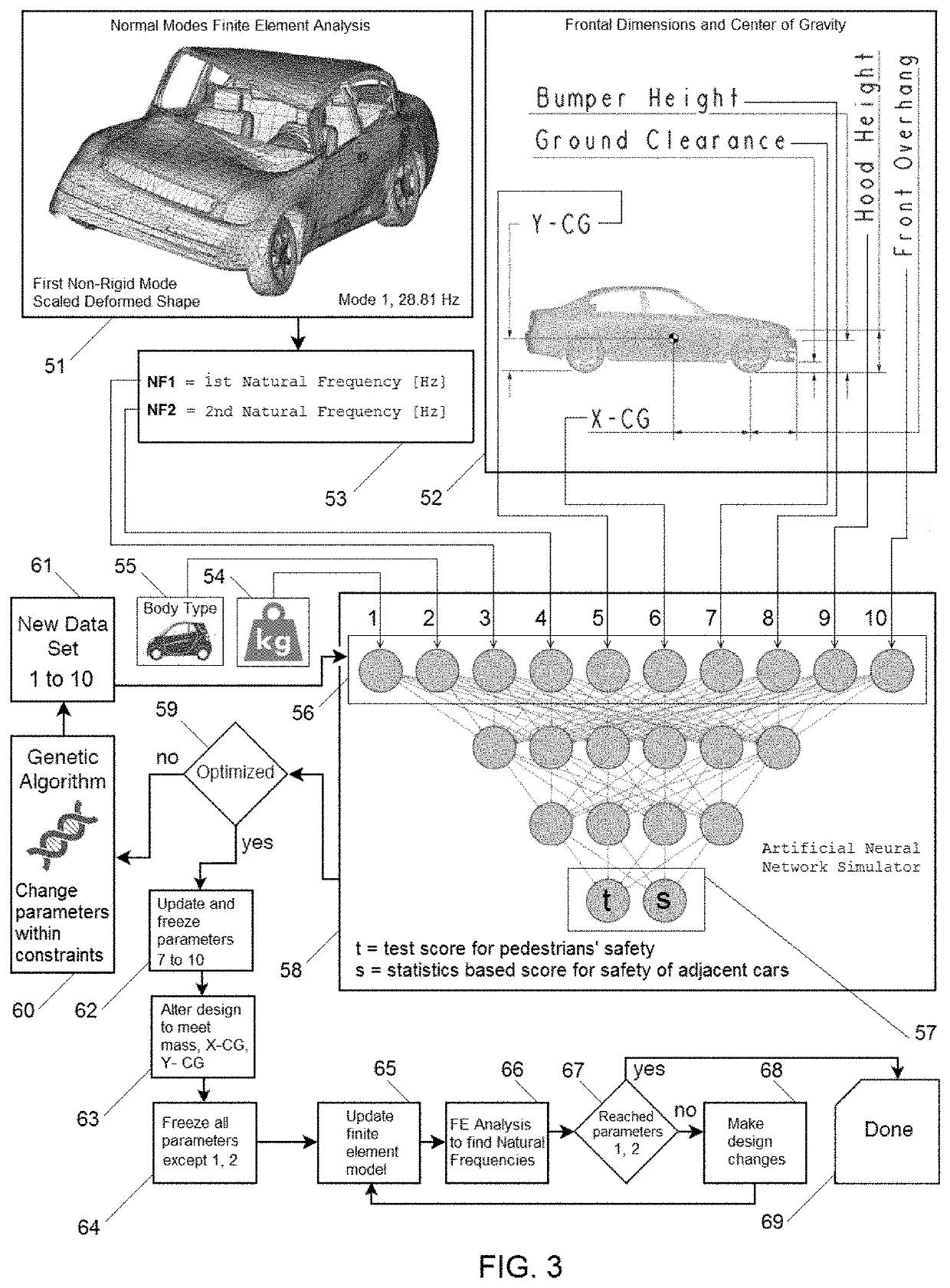
[0129]FIG. 3 shows the 2nd example. There are two optimization targets (57) in this example, indicated as (t): optimizing the car's design for pedestrians' safety test as indicated by crash test scores; and (s): optimizing the car's design for statistics-based safety score for passengers of adjacent cars which are involved in a crash situation with the optimized car. The second goal (s) is an example for the capability of the invention to simulate and optimize a new car based on safety aspects which cannot be simulated or tested using any existing method.

[0130]The finite element mesh is identical to the one used in example 1. However, only one analysis is performed for this example: a normal mode analysis of the unconstraint model. The first non-rigid-mode frequency in this example is 28.81 Hz, as shown in the deformed shape display (51). This frequency is marked as NF1 (53). Similar to the previous example, the required output from this modal analysis is the first two non-rigid-bod...

example 3

[0150]FIG. 4 shows example 3. There is only one optimization target (87) in this example, indicated as R: optimizing the car's design for rollover crash safety based on statistics data. This example demonstrates the ability to bypass test scores and optimize the car based on real-world data.

[0151]The finite element mesh is identical to the one used in examples 1 and 2. Similar to example 2, only one analysis is performed for this example: a normal mode analysis of the unconstraint model. The first non-rigid-mode frequency is marked as NF1 (83) and is one of the finite-element-related inputs (3) to be used for the input layer (85) of the neural network (86). However, in this example, additional output, which requires some additional postprocessing, is extracted from this analysis. The goal is a rollover crash safety, and, according to design experience as well as to common sense, the dynamic behavior of the frame of the windshield during such rollover crash situation is important. Fo...


PUM


Abstract

The present invention relates to a method for optimizing vehicles' design in terms of safety during crash situations, using a hybrid approach that combines analyzed data such as Finite Element data with methods from the AT fields, comprising the steps of: (a) collecting design data sets which include analyzed data; (b) collecting safety data of existing cars' models; (c) creating an Artificial Neural Network which learns how to predict safety data based on design data sets; (d) creating an optimizer which uses the neural network as a simulator and finds optimized values for design data sets of a new car's design; (e) performing a recurring process of design data set's update, until all parameters of the design data set get their optimized final values.

Description

FIELD OF THE INVENTION[0001]The field of the invention relates to a method and system for design optimization of vehicles. More particularly, the invention relates to a method and system for simulation of regular or autonomous vehicles, as part of the vehicle's development and design process, for the purpose of optimizing the vehicle in terms of safety during various crash situations and providing higher protection to the passengers of the car, as well as to surrounding cars and pedestrians. The invention combines a finite element analysis, an artificial neural network model, and a genetic algorithm. The invention introduces more functionality, more accuracy and faster performance comparing to any existing methods. Moreover, the invention can reveal dormant correlations between a car's design parameters and its expected safety. Such parameters relate not only to a car structure's strength, elasticity and durability, but also to many other potentially relevant, yet unknown, aspects o...

Claims


Application Information

Patent Timeline
IPC IPC(8): G06F17/50G01M5/00G06N3/04G05D1/00G06F17/18G06N3/12
CPCG06N3/126G05D1/0055G06F30/15G01M5/0033G06F30/23G06N3/04G06F17/18G06N3/08G06F30/27G06F2119/02G06F2119/14
Inventor VARON-WEINRYB, ABRAHAM
Owner VARON WEINRYB ABRAHAM
Learn More