Integrated thermal management module for vehicle

a technology of thermal management module and vehicle, which is applied in the direction of battery/fuel cell control arrangement, electrochemical generator, battery/fuel cell vehicle, etc., can solve the problems of unavoidable use of electric compressor for cooling and heat pump principle or separate electric heater for heating in these vehicles, and difficulty in using waste heat in electric vehicles or fuel cells, so as to reduce the resistance of cooling water and increase the cooling/heating efficiency

Active Publication Date: 2020-12-24
HYUNDAI MOTOR CO LTD +1
View PDF12 Cites 5 Cited by
  • Summary
  • Abstract
  • Description
  • Claims
  • Application Information

AI Technical Summary

Benefits of technology

[0007]Various aspects of the present invention are directed to providing an integrated thermal management module for a vehicle which is mounted on a vehicle, may be made compact by integrating complicated parts related to cooling water and a refrigerant into an assembly, and can increase cooling / heating efficiency by reducing the resistance of the cooling water or refrigerant.
[0023]According to an integrated thermal management module for a vehicle of the present invention, the integrated thermal management module is mounted on a vehicle, may be made compact by integrating complicated parts related to cooling water and a refrigerant into an assembly, and can increase cooling / heating efficiency by reducing the resistance of the cooling water or refrigerant.

Problems solved by technology

It is difficult to use waste heat in an electric vehicle or a fuel cell vehicle because there is no engine.
Accordingly, it is unavoidable to use an electric compressor for cooling and a heat pump principle or a separate electric heater for heating in these vehicles.
Accordingly, the cooling / heating circuit is somewhat complicated and several valves, pumps, and other parts are mounted in electric vehicles.

Method used


Image

  • Integrated thermal management module for vehicle
  • Integrated thermal management module for vehicle
  • Integrated thermal management module for vehicle

Examples


Embodiment Construction

[0030]Reference will now be made in detail to various embodiments of the present invention(s), examples of which are illustrated in the accompanying drawings and described below. While the present invention(s) will be described in conjunction with exemplary embodiments of the present invention, it will be understood that the present description is not intended to limit the present invention(s) to those exemplary embodiments. On the other hand, the present invention(s) is / are intended to cover not only the exemplary embodiments of the present invention, but also various alternatives, modifications, equivalents and other embodiments, which may be included within the spirit and scope of the present invention as defined by the appended claims.

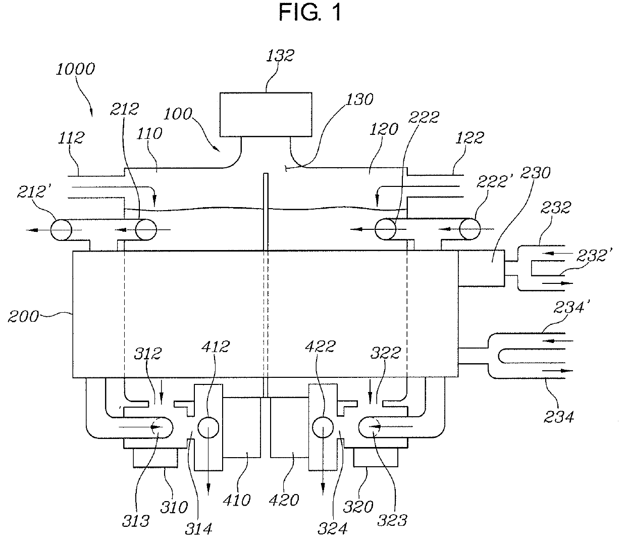
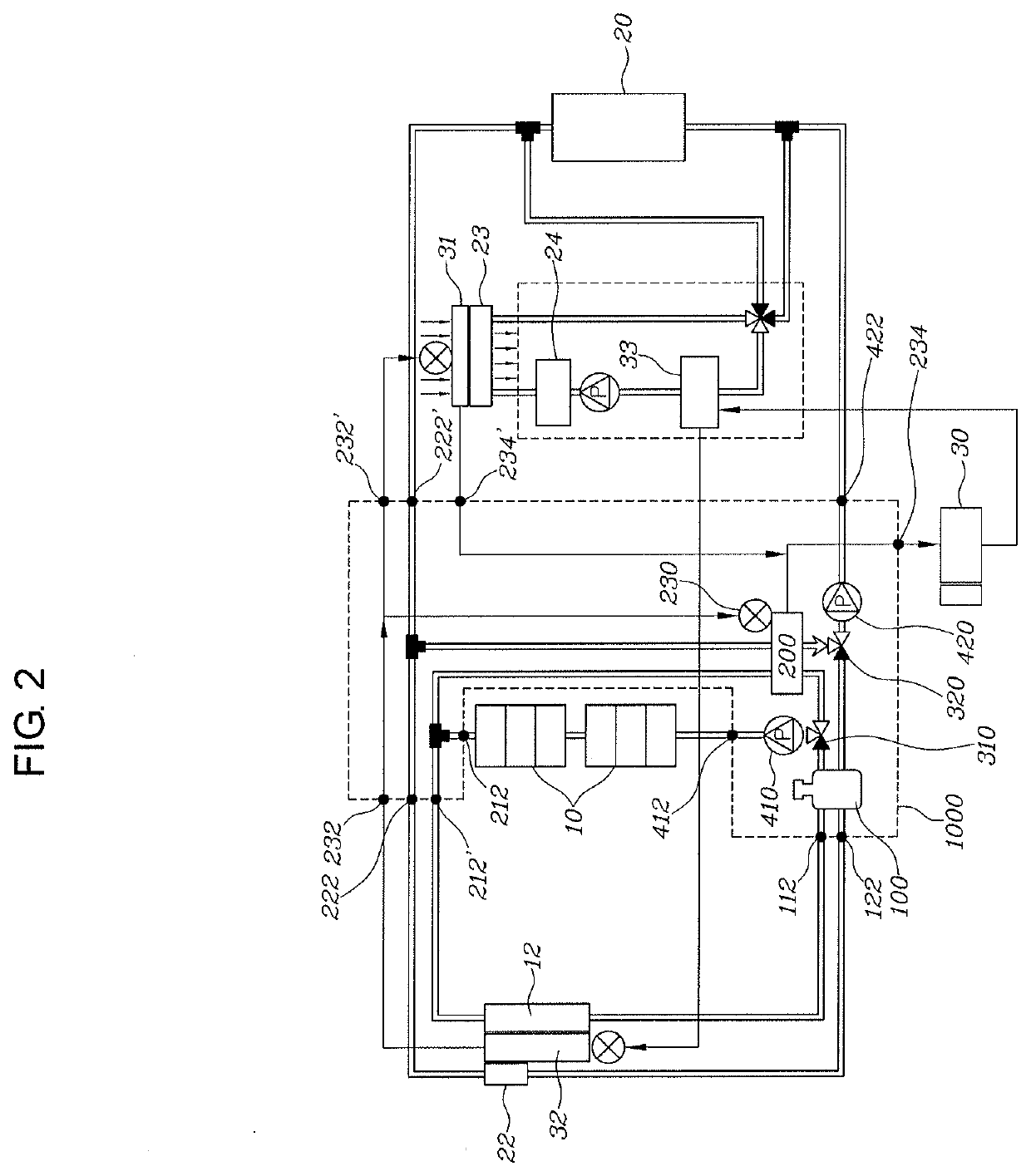
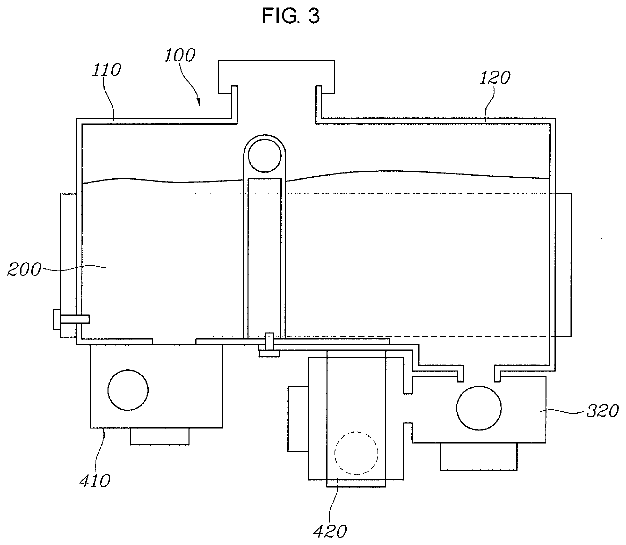
[0031]FIG. 1 is a view showing an integrated thermal management module for a vehicle according to an exemplary embodiment of the present invention, FIG. 2 is a view showing an automotive cooling / heating circuit to which the integrated thermal manag...


PUM

PropertyMeasurementUnit
distanceaaaaaaaaaa
resistanceaaaaaaaaaa
electrical energyaaaaaaaaaa

Abstract

An integrated thermal management module for a vehicle may include a chiller; a first reservoir portion through which electric part-cooling water passes, and a second reservoir portion through which high-voltage battery-cooling water passes; a first pump that circulates the electric part-cooling water through an electric portion, and a first valve that controls cooling water that has passed through the chiller or cooling water of the first reservoir portion to be selectively circulated through the electric portion by the first pump; and a second pump that circulates the high-voltage battery-cooling water through a high-voltage battery, and a second valve that controls the cooling water that has passed through the chiller or cooling water of the second reservoir portion to be selectively circulated through the high-voltage battery by the second pump.

Description

CROSS-REFERENCE TO RELATED APPLICATION[0001]The present application claims priority to Korean Patent Application No. 10-2019-0072604, filed on Jun. 19, 2019 in the Korean Intellectual Property Office, the entire contents of which is incorporated herein for all purposes by this reference.BACKGROUND OF THE PRESENT INVENTIONField of the Invention[0002]The present invention relates to an integrated thermal management module for a vehicle which is mounted on a vehicle, may be made compact by integrating complicated portions related to cooling water and a refrigerant into an assembly, and can increase cooling / heating efficiency by reducing the resistance of the cooling water or refrigerant.Description of Related Art[0003]It is difficult to use waste heat in an electric vehicle or a fuel cell vehicle because there is no engine. Accordingly, it is unavoidable to use an electric compressor for cooling and a heat pump principle or a separate electric heater for heating in these vehicles.[0004...

Claims


Application Information

Patent Timeline
Patent Type & Authority Applications(United States)
IPC IPC(8): B60H1/00H01M10/613H01M10/625H05K7/20
CPCB60H1/00278H05K7/20327H01M10/613H01M10/625B60H1/00392B60K1/00B60L58/26H01M10/615H01M10/6567H01M8/04029B60K2001/005B60H1/32284B60H1/3226B60H1/143B60H2001/00307Y02T10/70H01M10/6568H01M2220/20H01M10/63Y02E60/10Y02E60/50B60H1/00571B60H1/00885B60H1/00485B60H1/3228
Inventor OH, MAN JUCHUNG, SO LAKIM, JAE WOONGLEE, SANG SHIN
Owner HYUNDAI MOTOR CO LTD
Why Eureka
Try Eureka