Unlock instant, AI-driven research and patent intelligence for your innovation.
Intra-ruminal device
Pending Publication Date: 2021-01-07
ARGENTA MFG
View PDF0 Cites 1 Cited by
Summary
Abstract
Description
Claims
Application Information
AI Technical Summary
This helps you quickly interpret patents by identifying the three key elements:
Problems solved by technology
Method used
Benefits of technology
Benefits of technology
The present invention relates to an intra-ruminal device that can be used in ruminants for delivering active agents to the rumen. The device includes an elongate body or body assembly that is impervious to rumen fluids and has a barrel with a first end and a second end. It also includes at least one variable geometry device dependent from the body to assist rumen retention. The device can also have a cap with an outlet for accessing the rumen fluid. The attachment between the body and the cap can be achieved through an ultrasonic weld. The device can also have protrusions that provide a localized point of contact for the attachment. The technical effects of the invention include improved rumen retention, improved delivery of active agents to the rumen, and a simplified method of assembly.
Problems solved by technology
In conventional devices, the separation of device components within the rumen and / or after regurgitation remains a problem.
This is undesirable as internal separation of components may result in internal dose dumps, leading to toxicity to the animal and / or physical safety issues.
Separation of the device following regurgitation, such as if the device is crushed, could lead to other safety and environmental issues.
The efficacy of some conventional devices also continues to be limited due to pressure build-up inside the device leading to uncontrolled and inconsistent dosing.
Method used
Image
Click on the blue label to locate the original text in one second.
Reading with bidirectional positioning of images and text.
Examples
example 1
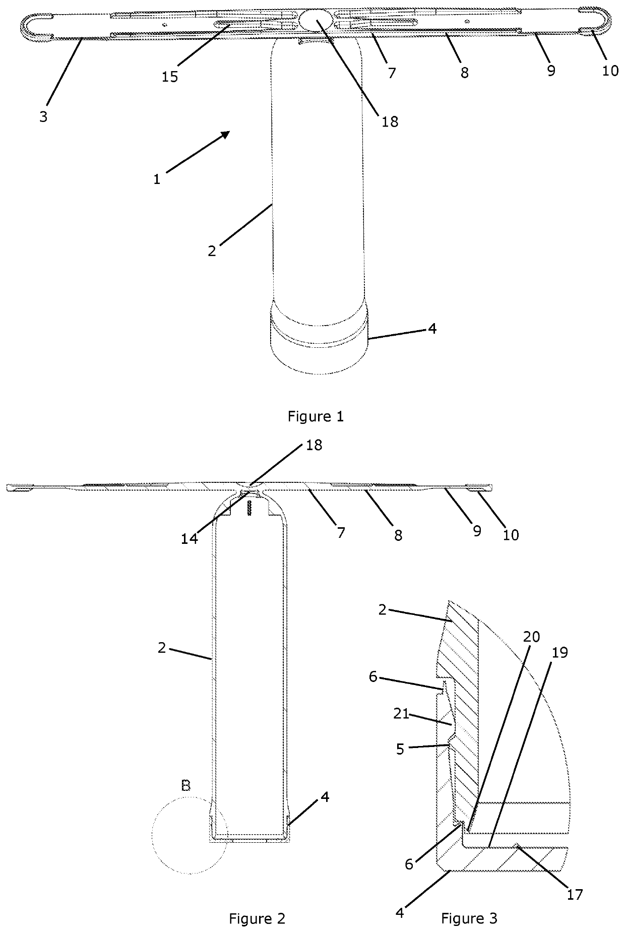
[0278]This example demonstrates the effect of modifying the cap protrusions.
[0279]Caps as shown in FIG. 3 were prepared. These caps comprise a thickened and blended wall section below the retention bead compared to test caps 1.
[0280]Intra-ruminal device bodies were constructed out of Bormed BE860MO resin and the intra-ruminal device bodies were ultrasonically welded to either the cap of FIG. 3 or test cap 1, both made of EP274P resin.
[0281]When the weld parameters of Table 2 were used some splitting was observed for test cap 1 but not the caps of FIG. 3.
[0282]Increasing the weld time to 0.34 s also resulted in successfully welded devices comprising the caps of FIG. 3 made of EP274P resin.
[0289]This example provides an example of welding configuration settings for ultrasonically welding a cap to the first end of the barrel of an intraruminal device.
[0290]Optionally, an ADG20 generator is used for an Ultrasonic Welder U149. The tables below provides an example of parameters which can be used.
Welding ModeEnergy modeThrottleFrom 3.5 to 7.0Amplitude (40-100% intern.From 95 to 100%Gain 1.5 × 2.027.00umTrigger (Pressure)0.6Welding Energy310.0WsHold Time600ms
example 3
[0292]This example provides a preferred configuration for the different physical characteristics of the different zones 7, 8, 9 of the resilient wing 3 design. Preferably the different zones of the resilient wing 3 comprises different flexibility characteristics. An advantage of the varying flexibility of the wing zones, is to provide the desired flexibility and strength properties at different zones of the wings 3. Preferably the wings 3 are separated into a first zone 7, a second zone 8, and a flexible zone 9.
[0293]Preferably, the capsules in this configuration comprises either Bormed or Sabic.
[0294]A peak force of 350-550 g was required to bend the flexible zone 9 and displace it by approximately 5 mm. A peak force of 1600-2600 g was required to bend the second zone 8 and displace it by approximately 5 mm. A peak force of 3500-5000 g was required to bend the second zone 8 and displace it by approximately 5 mm.
[0295]To test the wing 3 characteristics, the wings were cut to obtain ...
PUM
Property
Measurement
Unit
Fraction
aaaaa
aaaaa
Fraction
aaaaa
aaaaa
Fraction
aaaaa
aaaaa
Abstract
The invention relates to an intra-ruminal device comprising a cap, with outlet, that overlaps a portion of the barrel to define an attachment zone. Located within the attachment zone is at least one protrusion providing a localised point of contact between the barrel wall and the internal sidewall of the cap to provide for an ultrasonic weld between the barrel and the cap. Optionally the plunger comprises at least one aperture to allow fluid or gas communication between first and second compartments in the barrel. Optionally included are at least one pair of resilient wings, each pair of wings having a pair of reinforcement ridge that extend a first distance from the body along the wing surface, and at least one middle reinforcement ridge that extends between the pair of ridges from the body a second distance, and where the second distance is less than the first distance.
Description
FIELD OF THE INVENTION[0001]The present invention relates to an improved intra-ruminal device and method of making the device. In particular, the invention relates to an apparatus and method to improve the structural integrity of an intra-ruminal device and prevent the separation of various components of the device during and after use.BACKGROUND TO THE INVENTION[0002]An intra-ruminal controlled release device is a delivery device designed to provide therapeutic agents to the rumen over extended periods. To ensure the device performs as intended, certain Critical Quality Attributes (CQAs) must be met.[0003]CQAs include such requirements as (1) to keep the device intact so that the therapeutic agent is only exposed at an orifice, (2) to prevent damage to the rumen by individual components of the device (e.g. spring), and (3) to ensure the device remains in situ for the entire pay-out period.[0004]In conventional devices, the separation of device components within the rumen and / or aft...
Claims
Application Information
Patent Timeline
Application Date:The date an application was filed.
Publication Date:The date a patent or application was officially published.
First Publication Date:The earliest publication date of a patent with the same application number.
Issue Date:Publication date of the patent grant document.
PCT Entry Date:The Entry date of PCT National Phase.
Estimated Expiry Date:The statutory expiry date of a patent right according to the Patent Law, and it is the longest term of protection that the patent right can achieve without the termination of the patent right due to other reasons(Term extension factor has been taken into account ).
Invalid Date:Actual expiry date is based on effective date or publication date of legal transaction data of invalid patent.
