Arrangement for cooling an electric machine in a motor vehicle, and method for operating the arrangement

Active Publication Date: 2021-01-07
DR ING H C F PORSCHE AG
View PDF3 Cites 4 Cited by
  • Summary
  • Abstract
  • Description
  • Claims
  • Application Information

AI Technical Summary

Benefits of technology

[0013]The electric machine may be cooled differently in the different regions, specifically the rotor and the stator. More particularly, the stator may be cooled by the first cooling circuit, while the rotor is cooled by a second cooling circuit. The first cooling circuit may operate with a different medium than the second cooling circuit. The first cooling circuit may be formed by a motor vehicle cooling circuit, whereas the second cooling circuit may be formed by a transmission oil cooling circuit. The respective cooling media have a different viscosity. The cooling medium of the motor vehicle cooling circuit has a lower viscosity than the cooling medium of the transmission oil cooling circuit. The heat capacity of the transmission oil is thus relatively low.
[0014]Cooling of the stator may be carried out using a low-viscosity, electrically non-conductive medium,

Problems solved by technology

Power losses generated in components of electric machines are released in the form of heat, and the heat can affect

Method used


Image

  • Arrangement for cooling an electric machine in a motor vehicle, and method for operating the arrangement
  • Arrangement for cooling an electric machine in a motor vehicle, and method for operating the arrangement
  • Arrangement for cooling an electric machine in a motor vehicle, and method for operating the arrangement

Examples


Example

[0038]The second embodiment of FIG. 2 differs from the first embodiment of FIG. 1 only in that the connecting line 24 is connected, in the region upstream and downstream of the heat exchanger 10, to a bypass line 26. The bypass line 26 bridges the heat exchanger 10, but can be closed off by a closure 27. If the bypass line 26 is opened, the transmission oil no longer flows through the heat exchanger 10 owing to the relatively high pressure loss in relation to the bypass.

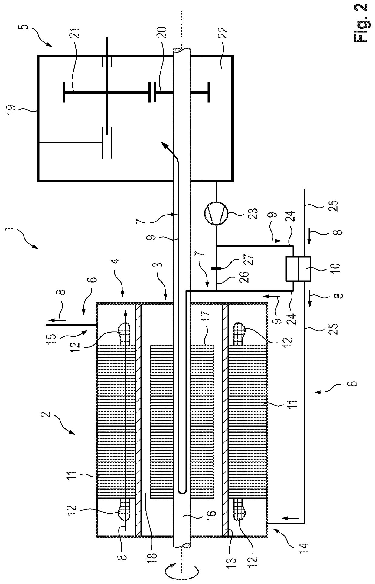
[0039]The embodiment of FIG. 1 constitutes the simplest variant, in which, in the vehicle, flow passes first through the heat exchanger 10 and then through the stator 4. The second embodiment of FIG. 2 constitutes a variant in which, when the bypass is open, little warming of the first coolant 8 passing through the heat exchanger 10 occurs, and thus particularly good cooling of the stator 4 is ensured. The closure 27 of the bypass line 26 may be a bypass valve for controlling the flow rate of the second cooling mediu...

Example

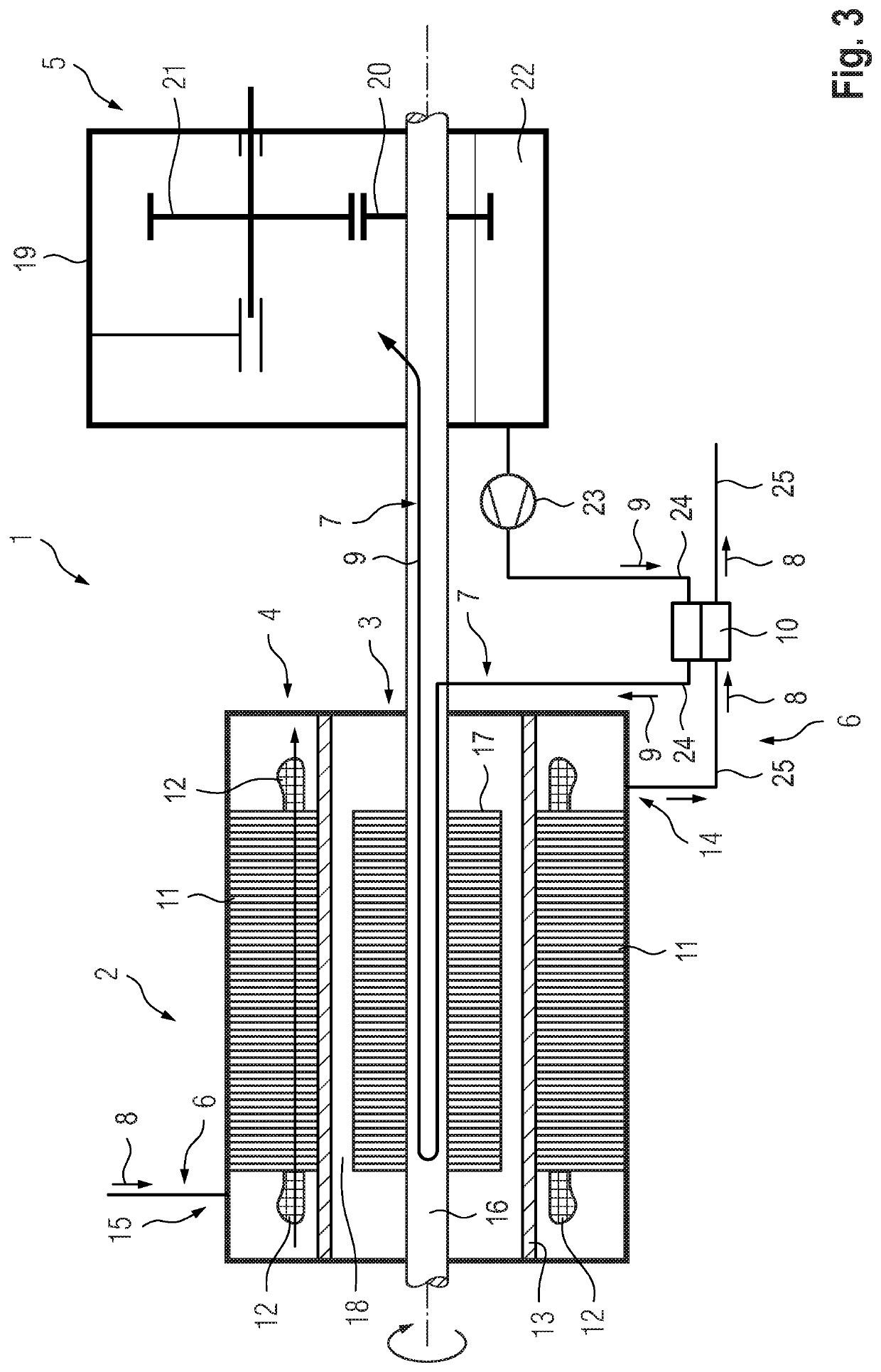
[0040]The third embodiment is illustrated in FIG. 3 and differs from the first exemplary embodiment of FIG. 1 merely in that the sequence of the throughflow in the first cooling circuit 6 has been changed. The first cooling medium 8 flows first through the stator 4 and then through the heat exchanger 10. This variant is used if fast heating of the transmission oil is desired.

Example

[0041]The fourth embodiment is illustrated in FIG. 4, and shows the first cooling circuit 6 and a switchable valve 28 in the form of a 4 / 2 directional valve. In the first switching position of the valve 28 shown in FIG. 1, relatively cold first cooling medium 8 flows via the connection 14 into the stator 4 and passes from the stator 4 via the connection 15 and from there via the heat exchanger 10 back to the valve 28. The connections 14 and 15 are arranged on the same side of the stator.

[0042]By contrast, in the second position of the valve 28 illustrated in FIG. 5, relatively cold first cooling medium 8 passes from the valve 28 via the heat exchanger 10 to the connection 15 and from there into the stator 4, and from the stator 4 via the connection 14 back to the valve 28.

[0043]The valve 28 can be operated to change the throughflow sequence of the stator 4 and the heat exchanger 10 in accordance with demand. The switching position shown in FIG. 4 warms the transmission oil with the ...


PUM


Abstract

A temperature control arrangement (1) of a motor vehicle has an electric machine (2) with a rotor (3) and a stator (4), a stator cooling arrangement with a first cooling circuit (6) for cooling the stator (4) with a first cooling medium (8) flowing in the first cooling circuit (6) that is formed by a motor vehicle cooling circuit, a rotor cooling arrangement with a second cooling circuit (7) for cooling the rotor (3) with a second cooling medium (9) flowing in the second cooling circuit (7) that is formed by a transmission oil cooling circuit, a heat exchanger (10) that thermally couples the first cooling circuit (6) and the second cooling circuit (7). The stator cooling arrangement is configured such that the first cooling medium (8) makes direct contact with the stator windings.

Description

CROSS REFERENCE TO RELATED APPLICATION[0001]This application claims priority under 35 USC 119 to German Patent Appl. No. 10 2019 117 637.9 filed on Jul. 1, 2019, the entire disclosure of which is incorporated herein by reference.BACKGROUNDField of the Invention[0002]The invention relates to an arrangement for cooling an electric machine of a motor vehicle.Related Art[0003]Power losses generated in components of electric machines are released in the form of heat, and the heat can affect the stator and the rotor of the electric machine. Known motor vehicles that are powered by an electric machine output the drive power of the electric machine via a transmission. Some of these known motor vehicles use relatively high viscosity transmission oil to dissipate the heat generated in the rotor and use a relatively low viscosity motor vehicle cooling medium to dissipate heat released by the stator. This motor vehicle cooling medium is cooled by a cooler of the cooling circuit of the motor veh...

Claims


Application Information

Patent Timeline
IPC IPC(8): H02K9/197B60K1/00B60K11/02F16H57/04H02K7/116
CPCH02K9/197B60K1/00B60K11/02B60K2001/006F16H57/0415H02K7/116F16H57/0476H02K1/20H02K1/32H02K9/19F16H57/0417F16H57/0435
Inventor STEINZ, JANINAOECHSLEN, STEFAN
Owner DR ING H C F PORSCHE AG
Why Eureka
Try Eureka