Until the mid to late 2000's, such computation systems and sensors with the required accuracy and multiple sensing axes were not available in the commercial and hobby markets, and were practicable only in larger aircraft or exotic systems such as military devices.
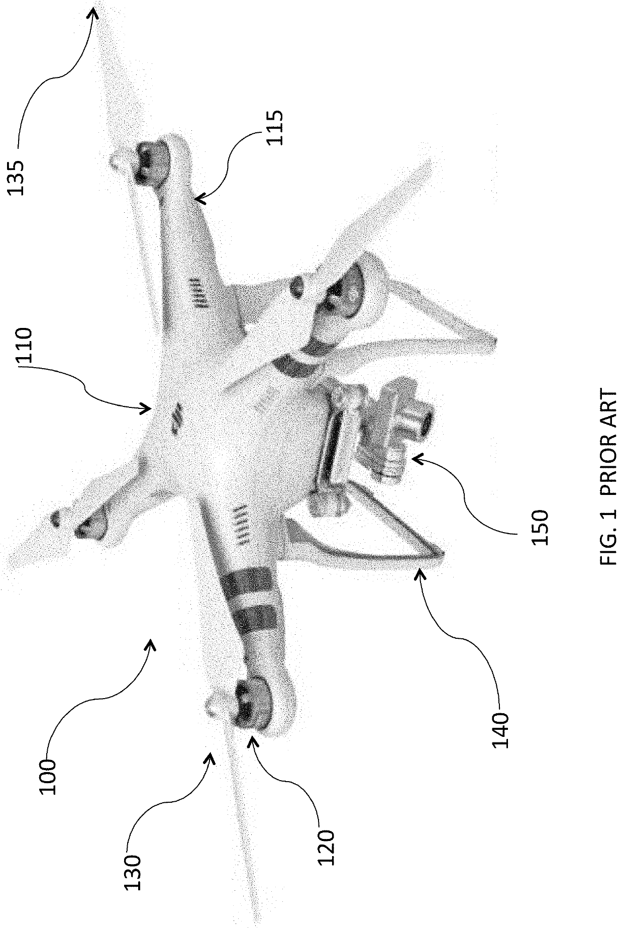
Examples of the costs of this configuration include:1. The entire area of a rotor's rotational coverage must be fully separated from all the other rotors, limiting the geometry of the vehicle and limiting the ratio of the effective rotor disk area to a relatively low fraction of the vehicle's overall
footprint.2. The use of fixed
pitch rotors limits the efficiency and operating conditions of the vehicle because the
angle of attack of the rotor blades cannot be controlled thus requiring the rotors to often be operated away from their best Lift / Drag
angle of attack.3. Because the electric motors cannot be operated at a constant peak efficiency RPM, the motors are often operated at reduced efficiency.4. To increase speed or
payload, the only options are to increase the output of the electric motors (which generally requires increasing the
mass of the motors), adding motors (accruing additional conversion losses), or increasing the rotor-blade size (further limiting the maneuverability of the vehicle because the rotational moment of inertial of the vehicle and the blade increases, and requiring a larger vehicle
footprint).5. Unless a complex
mechanical transmission was used to vary rotor speeds, it is not possible to use a centralized electrical motor to, among other reasons, decrease energy conversion losses.6. If all electrical power is lost, the vehicle will
crash because (unlike other rotary-wing aircraft) it is not possible to auto-rotate this kind of configuration.7. If an electrical motor failure occurs, the vehicle may be rendered uncontrollable.8. The provision of redundant mechanical power sources is impracticable because rotors are directly connected to the electrical motor shafts.9. The use of internal
combustion engines burning
high energy density
liquid fuel to ultimately power multiple electric motors is impractical or requires multiple conversion losses (due to electrical generation, storage inefficiencies, etc.) limiting the endurance,
payload and range of multi-
electric motor drones.
This performance is still inadequate for many potentially important commercial and industrial applications; thus designers turn to internal
combustion engines to provide more power.
However, these improvements have tended only to be available in larger vehicles of dramatically greater weight and cost.
Moreover, these vehicles tend to be large enough that a
truck must transport them.
However, there is a distinct lack of vehicles smaller than 9 feet in length or
diameter and less than about 200 pounds, which are able to carry payloads in the commercially desirable range from 10 to 30+ pounds.
Larger vehicles require dedicated transportation and handling crews.While it is well known that increasing the number of rotors can improve vehicle stability, there is a lack of multi-rotor vehicles with a high
power to weight ratio.
There is a lack of compact stable vehicles able to
handle applications with dense destabilizing payloads, such as chemical applications or weapons systems.There is also a distinct lack of small vehicles having a range greater than about 30 miles and endurance of more than 45 minutes, which are parameters needed to support numerous commercial and governmental mission profiles.While
liquid fuel provides the potential for greater
payload, range and speed, present liquid fueled UAS vehicles are much larger than battery powered vehicles.Compact, high rotor disc loaded vehicles are not available.
Such vehicles would be more stable in turbulence and able to carry heavier loads than now feasible in restricted areas.Vehicles with direct motor driven rotors cannot be configured with redundant power supplies and may become unstable if a motor fails.Vehicles with direct motor driven rotors are not capable of auto-rotation in the event of motor failure or power supply interruption.
This simplicity, however, places fundamental limits on the achievable
actuator bandwidth and the types of maneuvers possible to fly.
Removing the shrouds reduces the weight of the vehicle and increases
flight time.

