Alkaline dry batteries

Active Publication Date: 2021-01-14
PANASONIC INTELLECTUAL PROPERTY MANAGEMENT CO LTD
View PDF0 Cites 0 Cited by
  • Summary
  • Abstract
  • Description
  • Claims
  • Application Information

AI Technical Summary

Benefits of technology

[0031]FIG. 1 is a half sectional front view of an alkaline dry battery according to an embodiment of the present invention. FIG. 1 illustrates an example of cylindrical batteries having an inside-out structure. As illustrated in FIG. 1, the alkaline dry battery includes a hollow cylindrical positive electrode 2, a gelled negative electrode 3 disposed in the hollow portion of the positive electrode 2, a separator 4 arranged therebetween, and an electrolytic solution (not shown), and these are accommodated in a bottomed cylindrical battery case 1 that also serves as a positive electrode terminal. The electrolytic solution is an alkaline aqueous solution. A hydrophilic layer 10 is disposed between the positive electrode 2 and the inner surface of the battery case 1.
[0032]The positive electrode 2 is arranged in contact with the inner wall of the battery case 1 via the hydrophilic layer 10. The positive electrode 2 contains manganese dioxide and the electrolytic solution. The hollow portion of the positive electrode 2 is filled with the gelled negative electrode 3 via the separator 4. The negative electrode 3 contains a negative electrode active material including zinc, and usually further contains the electrolytic solution and a gelling agent.
[0033]The separator 4 has a bottomed cylindrical shape and contains the electrolytic solution. The separator 4 is composed of a cylindrical separator and a bottom paper. The separator 4 is arranged along the inner surface of the hollow portion of the positive electrode 2 and separates the positive electrode 2 and the negative electrode 3 from each other. Thus, the separator arranged be

Problems solved by technology

Alkaline dry batteries have a drawback in that the discharge time is very short when the batteries are discharged in a low-temperature environment.
Even the alkaline dry battery described in Patent Literature 1 has a poor discharge performance in a low-temperature environment.
That is, the outer peripheral portion of the positive electrode is not effectively used, and the positive el

Method used


Image

  • Alkaline dry batteries

Examples


example 1

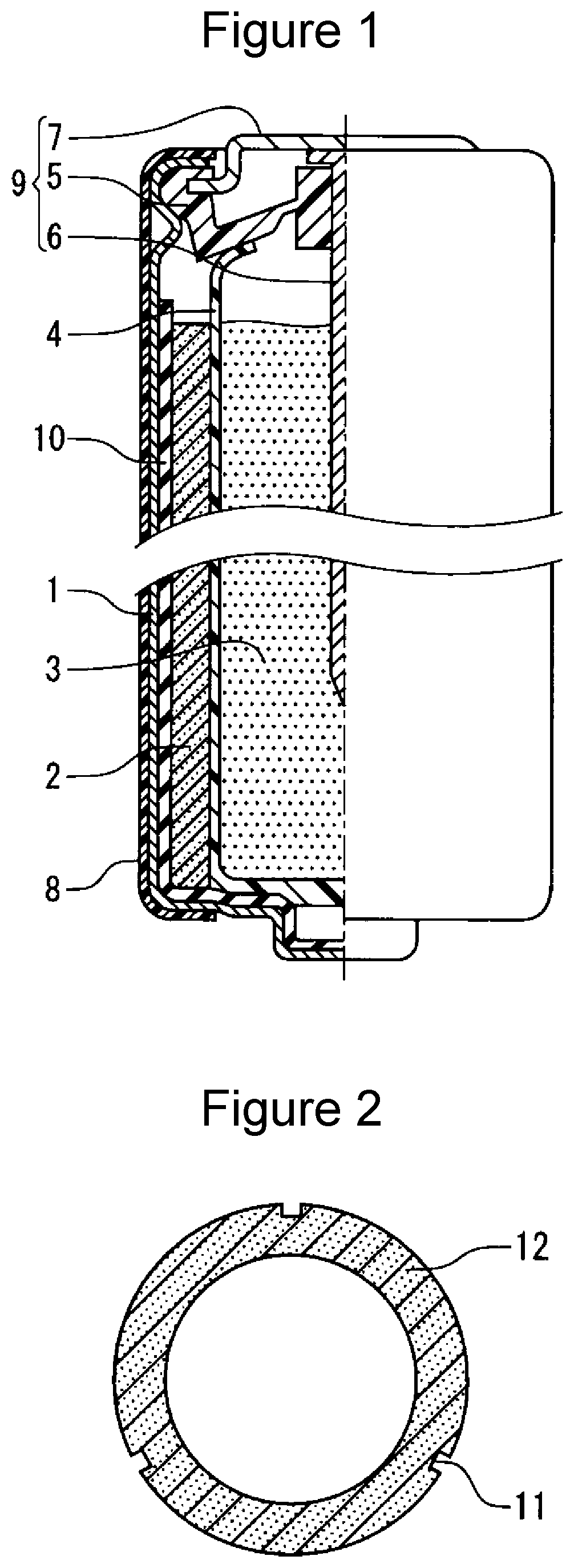
[0062]Cylindrical AA alkaline dry batteries (LR6) illustrated in FIG. 1 were produced in accordance with the following procedures (1) to (4).

[0063](1) Fabrication of Positive Electrode

[0064]A graphite powder (average particle size (D50): 8 μm) as a conductive agent was added to an electrolytic manganese dioxide powder (average particle size (D50): 35 μm) as a positive electrode active material to give a mixture. The mass ratio of the electrolytic manganese dioxide powder to the graphite powder was 92.4:7.6. The electrolytic manganese dioxide powder used had a specific surface area of 41 m2 / g. 1.5 Parts by mass of an electrolytic solution was added to 100 parts by mass of the mixture, and the resultant mixture was sufficiently stirred and compacted into flakes. A positive electrode mixture was thus obtained. The electrolytic solution used was an alkaline aqueous solution containing potassium hydroxide (concentration: 35 mass %) and zinc oxide (concentration: 2 mass %).

[0065]The flaky...

example 5

[0085]A granular positive electrode mixture was compacted using a predetermined mold to give two hollow cylindrical positive electrode pellets 12 illustrated in FIG. 2. The positive electrode pellet 12 had three recesses 11 on its outer peripheral surface. The three recesses 11 were disposed at regular intervals in a cross section perpendicular to the axial direction of the positive electrode pellet 12, and each recess extended along the axial direction of the positive electrode pellet 12. The three recesses were 0.5 mm in depth and 1 mm in width.

[0086]A hydrophilic layer was formed on the inner surface of a battery case in the same manner as in EXAMPLE 1. The two positive electrode pellets 12 were vertically inserted into the battery case. During this process, the recesses 11 in the two positive electrode pellets 12 were aligned with one another using a predetermined jig. Thereafter, the two positive electrode pellets were pressed to form a positive electrode in close contact with ...

example 6

[0088]Two hollow cylindrical positive electrode pellets having three recesses on the outer peripheral surface were fabricated in the same manner as in EXAMPLE 5. A hydrophilic layer was formed on the inner surface of a battery case in the same manner as in EXAMPLE 2. The two positive electrode pellets were vertically inserted into the battery case while aligning the recesses of the two positive electrode pellets with one another. Thereafter, the two positive electrode pellets were pressed to form a positive electrode in close contact with the inner wall of the battery case.

[0089]An alkaline dry battery A6 was fabricated and evaluated in the same manner as in EXAMPLE 1 except for the above. The content Ma and content Mb of the hydrophilic material were as described in Table 2.

[0090]The evaluation results are described in Table 2. Table 2 also shows the evaluation results of the batteries A1 and A2 of EXAMPLES 1 and 2.

TABLE 2DischargeContent MaContent Mbperformance(mass %) of(mg / cm2) ...


PUM


Abstract

An alkaline dry battery includes a battery case, a hollow cylindrical positive electrode accommodated in the battery case, a negative electrode disposed in the hollow portion of the positive electrode, a separator disposed between the positive electrode and the negative electrode, and an electrolytic solution contained in the positive electrode, the negative electrode and the separator. The alkaline dry battery further includes a layer principally including a compound containing a polyoxyethylene group between the positive electrode and the inner surface of the battery case.

Description

TECHNICAL FIELD[0001]The present invention relates to an improvement of the discharge performance of an alkaline dry battery in a low-temperature environment.BACKGROUND[0002]Alkaline dry batteries (alkaline manganese dry batteries) have a larger capacity and can draw a larger current than manganese dry batteries, and thus have found widespread use. An alkaline dry battery includes a battery case, a hollow cylindrical positive electrode accommodated in the battery case, a negative electrode disposed in the hollow portion of the positive electrode, a separator disposed between the positive electrode and the negative electrode, and an electrolytic solution contained in the positive electrode, the negative electrode and the separator. The electrolytic solution that is used is an aqueous solution of potassium hydroxide or the like, and exhibits a good viscosity and good ion conductivity in a room temperature environment around 20° C.[0003]Patent Literature 1 discloses that a conductive l...

Claims


Application Information

Patent Timeline
IPC IPC(8): H01M6/06H01M2/02H01M4/06H01M6/02H01M50/107H01M50/117H01M50/119H01M50/121H01M50/122H01M50/124H01M50/126H01M50/131
CPCH01M6/06H01M2/0287H01M4/06H01M2220/30H01M2/022H01M6/02H01M2/026H01M6/085H01M6/24H01M2300/0082H01M2300/0002H01M50/121H01M50/124H01M50/119H01M50/117H01M50/126H01M50/107H01M50/122H01M50/131Y02E60/10H01M50/116
Inventor TAKAHASHI, YASUFUMIKUSUMOTO, YASUYUKIFUKUI, ATSUSHI
Owner PANASONIC INTELLECTUAL PROPERTY MANAGEMENT CO LTD
Why Eureka
Try Eureka