Heat shield assembly for an epitaxy chamber
Active Publication Date: 2021-01-14
APPLIED MATERIALS INC
0 Cites 0 Cited by
AI-Extracted Technical Summary
Problems solved by technology
The substrate may be configured to rotate during processing to minimize the effect of non-uniformities, but persistent non-uniformities may nonetheless manifest as radial variations.
As the thickness of the residual material deposits grow, the deposits eventually flake from the epitaxy processing chamber surfaces leading to undesirable particula...
Method used
[0019]A portion of the annular opening is not overlapped by the heat shield member. The position of the non-overlapped portion of the annular opening with respect to a gas inlet and a gas outlet influences a coating of deposition material on surfaces within the internal volume. More specifically, positioning the heat shield member distally from the gas outlet reduces the coating of deposition material on the substrate support, on the upper dome surfaces and lower dome surfaces of the processing chamber. Because the position of the annular opening reduces the deposition of material on surfaces within the interior volume of the processing chamber, a maintenance cycle for cleaning the surfaces within the interior volume of the processing chamber is lengthened or improved. The reduction in deposition material on the upper and lower dome and substrate support enables longer intervals between performing in situ cleaning cycles for the interior volume. By reducing periodic maintenance and having longer cycles between in situ cleaning, a higher throughput is achieved. The examples disclosed herein additionally enable improved process stability by reducing the undesirable coating within the chamber. Accordingly, the cost of ownership for the processing chamber is reduced as the mean time between service intervals is extended.
[0025]The substrate support 104 is configured to support a substrate 108 disposed on an upper surface 110 of the substrate support 104 during processing operations in the processing chamber 100. The substrate support 104 may rotate the substrate 108 during processing to improve the uniformity of material deposited on the substrate 108. The upper dome 128 is disposed above the substrate support 104 and together with the upper surface 110 of the substrate support 104 and the liner 163 further define the processing volume 111. The purge volume 113 is further defined by the lower dome 114, a bottom surface (not shown) of the substrate support 104, and the liner 163.
[0030]Gases flowing from the process gas inlet 174 and purge gas inlet 164 enter the processing chamber 100 at velocity that is greater than the velocity of gases escaping through the gas outlet 178. Gases in the purge volume 113 proximate the gas outlet 178 have lower velocity and mass flow rate. Similarly, gases in the processing volume 111 proximate the gas outlet 178 have lower velocity and mass flow rate. The lower velocities and mass flow rates at the gas outlet 178 help reduce pressure variances (described below with respect to FIG. 3) across the arc-shaped aperture 232. The lower pressure variances at the annular opening 134 facilitate the uniform deposition of material on the substrate 108 in the processing volume because the decrease in pressure variance at the annular opening 134 reduces the opportunity for purge gas to enter the processing volume 111. Similarly, the reduction in pressure variance across the annular opening 134 reduces the opportunity for the processing gas to enter the purge volume 113. Thus, the pressure variance at the arc-shaped aperture 232 of the heat shield assembly 160 affects the azimuthal pressure profile of...
Abstract
Disclosed herein is a heat shield assembly for a processing chamber. The processing chamber includes a body having sidewalls, a bottom and a lid that define an interior volume. The heat shield assembly is disposed in the interior volume, and includes a heat shield and a preheat member. The preheat member includes an inner circumference, and is positioned below the heat shield. A susceptor is disposed in the interior volume and configured to support a substrate, and is positioned within the inner circumference of the preheat member. An opening is positioned between the susceptor and the preheat member. A first section of the opening is proximate to a gas inlet, and is covered by the heat shield. A second section of the annular opening is proximate a gas outlet, and is not covered by the heat shield member.
Application Domain
Semiconductor/solid-state device manufacturingFrom chemically reactive gases +2
Technology Topic
PhysicsEngineering +3
Image
Examples
- Experimental program(1)
Example
[0017]In order to facilitate understanding, identical reference numerals have been used, where possible, to designate identical elements that are common features. It is contemplated that elements and features of one example may be beneficially incorporated into other examples without further recitation.
DETAILED DESCRIPTION
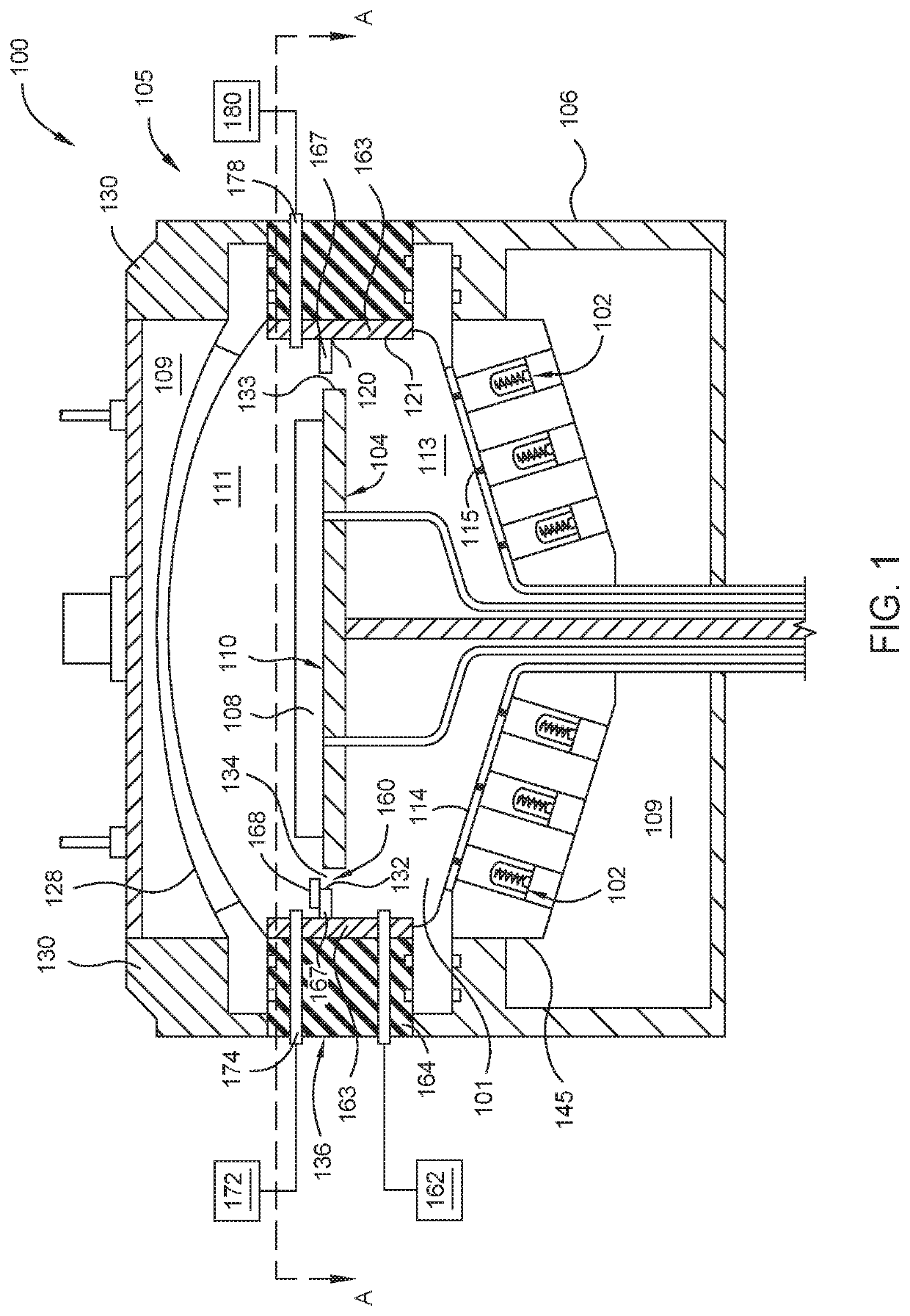
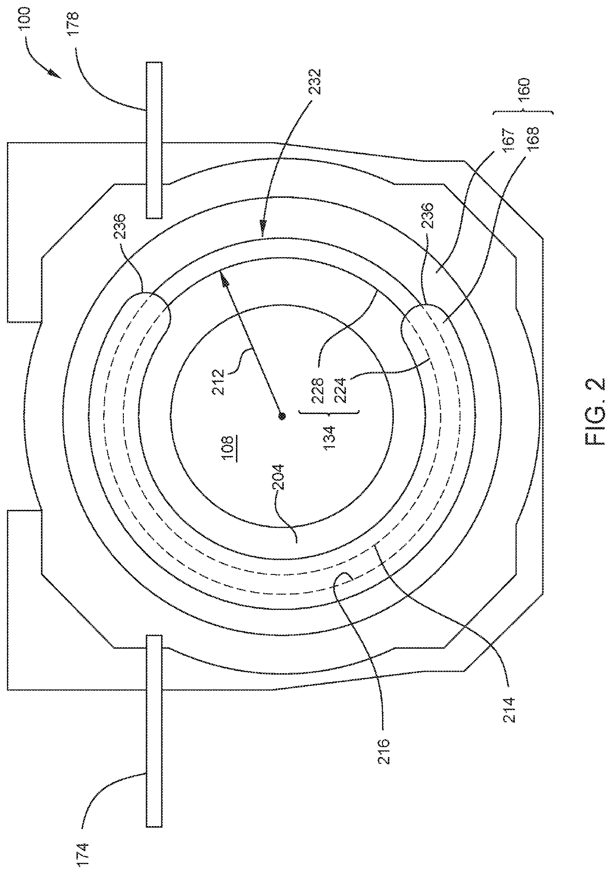
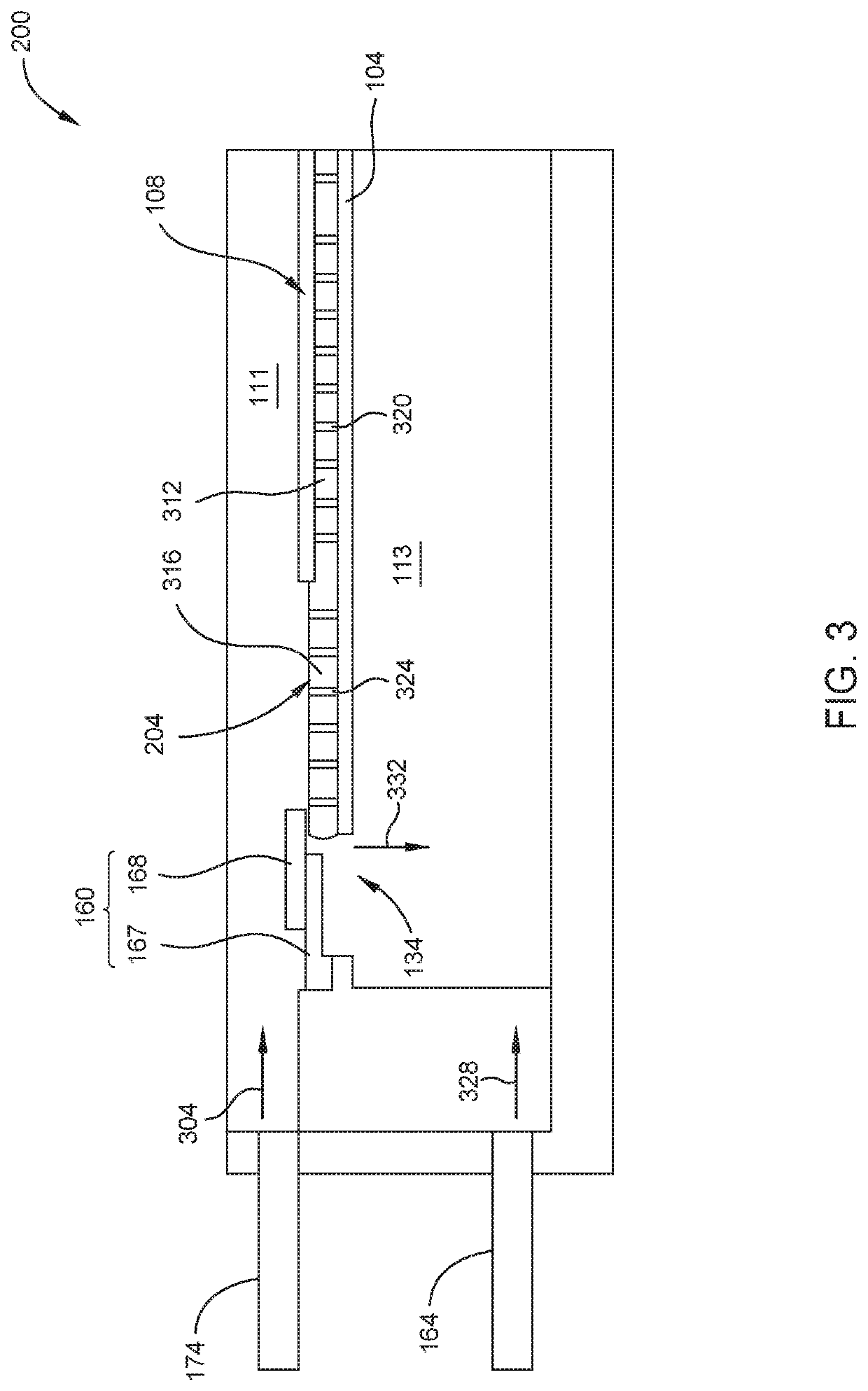
[0018]Disclosed herein is a heat shield assembly for a processing chamber. Examples of the processing chamber include a chamber body having sidewalls, a bottom and a lid defining an interior volume of the chamber body. Disposed within the internal volume is a substrate support and the heat shield assembly. The heat shield assembly includes a heat shield member and an annular preheat member. An annular opening is formed between the substrate support and the annular preheat member.
[0019]A portion of the annular opening is not overlapped by the heat shield member. The position of the non-overlapped portion of the annular opening with respect to a gas inlet and a gas outlet influences a coating of deposition material on surfaces within the internal volume. More specifically, positioning the heat shield member distally from the gas outlet reduces the coating of deposition material on the substrate support, on the upper dome surfaces and lower dome surfaces of the processing chamber. Because the position of the annular opening reduces the deposition of material on surfaces within the interior volume of the processing chamber, a maintenance cycle for cleaning the surfaces within the interior volume of the processing chamber is lengthened or improved. The reduction in deposition material on the upper and lower dome and substrate support enables longer intervals between performing in situ cleaning cycles for the interior volume. By reducing periodic maintenance and having longer cycles between in situ cleaning, a higher throughput is achieved. The examples disclosed herein additionally enable improved process stability by reducing the undesirable coating within the chamber. Accordingly, the cost of ownership for the processing chamber is reduced as the mean time between service intervals is extended.
[0020]In this disclosure, the terms “top”, “bottom”, “side”, “above”, “below”, “up”, “down”, “upward”, “downward”, “horizontal”, “vertical”, and the like do not refer to absolute directions. Instead, these terms refer to directions relative to a basis plane of the chamber, for example a plane parallel to a surface of the substrate of the processing chamber.
[0021]FIG. 1 is a schematic cross-sectional view of a processing chamber 100 having a heat shield assembly 160. The processing chamber 100 has a chamber body 105. The chamber body 105 includes sidewalls 136, a bottom 106, and a lid 130 that define an enclosure 109 of the chamber body 105. An upper dome 128, lower dome 114, and liners 163 are disposed in the enclosure 109. The liners 163 are affixed to the sidewalls 136. An internal volume 101 of the chamber body 105 is defined by the upper dome 128, the lower dome 114, and the liners 163. The internal volume 101 includes a processing volume 111 and a purge volume 113.
[0022]A process gas inlet 174 is formed through the sidewalls 136 of the processing chamber 100. The process gas inlet 174 is also formed through the liner 163 and provides a pathway to flow process gases into the processing volume 111. Process gases flow from a gas source 172 through the process gas inlet 174 and across a substrate support 104 disposed within the internal volume 101 of the processing chamber 100.
[0023]A purge gas inlet 164 is coupled to a purge gas source 162. The purge gas inlet 164 is also formed through the liner 163 and provides a pathway to flow purge gases into the purge volume 113. Purge gases flow from the purge gas source 162 through the purge gas inlet 164.
[0024]A gas outlet 178 is disposed through the sidewall 136 and the liner 163 is substantially opposite the process gas inlet 174 in the internal volume 101 of the processing chamber 100. The gas outlet 178 enables process gases in the processing volume 111 of the internal volume 101 to be evacuated from the processing chamber 100. Purge gases within the purge volume 113 of the internal volume 101 are evacuated from the processing chamber 100 through the gas outlet 178. A vacuum source 180 is coupled to the gas outlet 178 to evacuate the process and purge gases from the internal volume 101 of the processing chamber 100.
[0025]The substrate support 104 is configured to support a substrate 108 disposed on an upper surface 110 of the substrate support 104 during processing operations in the processing chamber 100. The substrate support 104 may rotate the substrate 108 during processing to improve the uniformity of material deposited on the substrate 108. The upper dome 128 is disposed above the substrate support 104 and together with the upper surface 110 of the substrate support 104 and the liner 163 further define the processing volume 111. The purge volume 113 is further defined by the lower dome 114, a bottom surface (not shown) of the substrate support 104, and the liner 163.
[0026]A heat module 145 provides heat to the processing chamber 100 during processing. The heat module 145 may be positioned above or below the substrate support 104. In the processing chamber 100 illustrated in FIG. 1, the heat module 145 is provided below the substrate support 104. The heat module 145 may include optical elements 115, such as lenses, light pipes, or other reflective and refractive elements. The heat module 145 includes a plurality of heat sources 102. The plurality of heat sources 102 is disposed within the lower dome 114. The heat sources 102 may be any combination of lamps, light emitting diodes (LEDs), and lasers. The reflective and refractive elements are individually shaped to direct the energy emitted by the heat source 102 toward the substrate support 104. The heat from the heat module 145 heats the substrate support 104, which transfers heat to the substrate 108 by conduction where the substrate 108 is in contact with the substrate support 104. In some cases, heat may also be transferred by radiation, for example where the substrate 108 does not contact the substrate support 104.
[0027]The heat shield assembly 160 surrounds the substrate support 104. The heat shield assembly 160 is an annular or ring-like structure concentric with the substrate support 104. An outer radius 120 of the heat shield assembly 160 is less than an inner radius 121 of the liner 163, such that the heat shield assembly 160 fits within the inner radius of the liner 163.
[0028]The heat shield assembly 160 includes the annular preheat member 167 and a heat shield member 168. The annular preheat member 167 is annular or ring shaped. The annular preheat member 167 has an inner radius 132 that is larger than an outer radius 133 of the substrate support 104. The heat shield member 168 is shaped like a sector of an annular ring, i.e., arc shaped. The heat shield member 168 has edges (236 in FIG. 2.) which define the ends of the sector. An annular opening 134 is disposed between the annular preheat member 167 and the substrate support 104. As described in further details below, the heat shield member 168 vertically overlaps a portion of the annular opening 134.
[0029]FIG. 2 is a plan view of the processing chamber 100, as viewed along section line A-A in FIG. 1. The substrate support 104 has a susceptor 204. In some examples, the susceptor 204 is integral to or part of the substrate support 104. Alternately, the susceptor 204 may be coupled to the substrate support 104 in a manner that enables the susceptor 204 to be moveably detached from the substrate support 104. The susceptor 204 has an outer circumference 214 that is defined by a radius 212. An inner circumference 216 of the annular preheat member 167 is defined by its inner radius 132. The annular opening 134 is defined by a space between the outer circumference 214 of the susceptor 204 and the inner circumference 216 of the annular preheat member 167. The annular opening 134 includes a first part 224 and a second part 228. The first part 224 of the annular opening 134 is covered by the heat shield member 168. The process gas inlet 174 is proximate the first part 224 of the annular opening 134. The second part 228 of the annular opening 134 is not covered by the heat shield member 168. The gas outlet 178 is proximate the second part 228 of the annular opening 134. The second part 228 of the annular opening 134 is an arc-shaped aperture 232. The arc-shaped aperture 232 is a space defined by the outer circumference of the susceptor 204, the inner circumference 216 of the annular preheat member 167, and the edges 236 of the heat shield member 168. Thus, the heat shield member 168 prevents direct line of sight from the processing volume 111 to the purge volume 113 through only the first part 224 of the annular opening 134.
[0030]Gases flowing from the process gas inlet 174 and purge gas inlet 164 enter the processing chamber 100 at velocity that is greater than the velocity of gases escaping through the gas outlet 178. Gases in the purge volume 113 proximate the gas outlet 178 have lower velocity and mass flow rate. Similarly, gases in the processing volume 111 proximate the gas outlet 178 have lower velocity and mass flow rate. The lower velocities and mass flow rates at the gas outlet 178 help reduce pressure variances (described below with respect to FIG. 3) across the arc-shaped aperture 232. The lower pressure variances at the annular opening 134 facilitate the uniform deposition of material on the substrate 108 in the processing volume because the decrease in pressure variance at the annular opening 134 reduces the opportunity for purge gas to enter the processing volume 111. Similarly, the reduction in pressure variance across the annular opening 134 reduces the opportunity for the processing gas to enter the purge volume 113. Thus, the pressure variance at the arc-shaped aperture 232 of the heat shield assembly 160 affects the azimuthal pressure profile of the processing gasses across the substrate 108. In this manner, the position of the arc-shaped aperture 232 reduces the unwanted deposition of material on internal surfaces of the lower dome 114, upper dome 128, and liner 163. Positioning the arc-shaped aperture 232 proximate the gas outlet 178 enables a reduction in the amount of undesired deposition materials on internal surfaces of the processing chamber 100.
[0031]FIG. 3 is a schematic cross-sectional view of the processing chamber 100 in the vicinity of the gas inlet, depicted in FIG. 1. In some examples, the susceptor 204 can be supported by the substrate support 104. The susceptor 204 may have a recessed portion 312 having through-holes 320. The recessed portion 312 is configured to support the substrate 108 in a vertical direction. The susceptor 204 may also have a raised portion 316 that has a plurality of openings 324. The raised portion 316 of the substrate support 104 holds the substrate 108 in a lateral direction, thus preventing the substrate from sliding in a horizontal or radial direction. A diameter of each opening 324 is larger than a diameter of each through-hole 320. The raised portion 316 surrounds the substrate 108.
[0032]A process gas 304 enters the processing volume 111 from the process gas inlet 174 at a given pressure. The process gas 304 is generally drawn over the substrate 108 toward the gas outlet 178. A purge gas 328 is pressurized and enters the purge volume 113 through the purge gas inlet 164. Because the process gas 304 gas and the purge gas 328 enter the processing chamber 100 under pressure, differences in pressure may create a pressure variance 332 in the region of the annular opening 134. Moreover, because the velocities of the purge gas 328 and the process gas 304 are higher near the process gas inlet 174 and purge gas inlet 164, the mass flow rate is also increased in the area near the process gas inlet 174 and purge gas inlet 164.
[0033]The heat shield member 168 is positioned vertically above the annular opening 134 to reduce the pressure variance 332 in the area of the annular opening 134. The reduction in pressure variance 332 reduces the opportunity for purge gas 328 to enter the processing volume 111. Thus, the lower pressure variance 332 facilitates uniform deposition of material on the substrate 108 in the processing volume 111.
[0034]FIG. 4 is a top view of the heat shield assembly 160 utilized in the processing chamber of FIG. 1. The heat shield member 168 rests on the annular preheat member 167. The inner circumference 216 of the heat shield member 168 extends inward to cover the annular opening 134. Thus, the inner circumference 216 of the annular preheat member 167 is larger than the inner radius 412 of the heat shield member 168. An outer radius 410 of the annular preheat member 167 is also larger than an outer radius 424 of the heat shield member 168.
[0035]The heat shield member 168 has a gap 420 that exposes a portion 422 of the annular preheat member 167. That is, the gap 420 represents a sector which in addition to the heat shield member 168 would complete an annular ring shape. However, it should be appreciated that the gap 420 is not a segment or other shape but merely the opening in the heat shield member 168 and thus can equally be described as any shape that would be accepted through said opening in the heat shield member 168. The exposed portion 422 provides more direct heat exposure for gases flowing from the process gas inlet 174 towards the gas outlet 178, across the annular preheat member 167 to the substrate support 104 by placing exposed portion 422 proximate the gas outlet 178. Process gas 304 flowing from the process gas inlet 174 toward the gas outlet 178 are directly exposed to purge gas 328 flowing from the purge gas inlet 164 toward the gas outlet 178. The inner circumference 216 of the heat shield member 168 may be more than 150 mm to accommodate a substrate having a nominal diameter of 300 mm. For example, the inner circumference 216 may be from about 151 mm to about 155 mm for a substrate that is 300 mm in diameter. In some examples, the substrate may be 6 inches or 8 inches. Accordingly, the substrate may have a diameter from about 150 mm to about 300 mm. The gap 420 may have a dimension selected to provide a desired amount of heat exposure to gases exiting the processing chamber 100 at the gas outlet 178.
[0036]Turning to FIG. 5, FIG. 5 is a schematic top view of the heat shield member 168 of the heat shield assembly 160 utilized in the processing chamber 100 of FIG. 1. The gap 420 is shown having a dimension 502. The dimension 502 may have a width from about 50 mm to about 180 mm. The dimension 502 of the gap 420 corresponds to the arc-shaped aperture 232 depicted in FIG. 2. Accordingly, a ratio 620 of the gap 420 to substrate radius 240 also corresponds to the uniformity of deposition thickness observed in FIG. 7 and discussed below.
[0037]The gap 420 has a first edge 504 and a second edge 506. The first edge 504 and second edge 506 of the gap 420 corresponding to the edges 236 of the heat shield member 168. The first edge 504 and the second edge 506 are generally parallel to a radial line 508 that bisects an angle 510 subtended by the gap 420. The gap 420 promotes uniform laminar flow of the process gas 304 and purge gas 328. In other examples, the edges 504 and 506 may have any desired directionality. For example, each edge 504 or 506 may be parallel to the radial line 508 that intersects with the respective edge 504 or 506. Either the first edge 504 or the second edge 506 may have a feature 512 to prevent movement of the heat shield member 168 during operation of the processing chamber 100. In another example, two outer corners of edges 504 and 506 on either side of the gap 420 have a rounded shape, i.e., the features 512. The rounded corners of the features 512 are circular, but any desired shape may be added to the corners of either edge 504 or 506. For example, the features 512 may be a chamfer of any suitable angle. The rounded corners of the features 512 have a radius of curvature of between about 0.01 mm and about 1.5 mm, such as between about 0.1 mm and about 1.0 mm, for example about 0.3 mm, 0.4 mm, or 0.5 mm.
[0038]FIG. 6 is a graph 600 depicting deposition thickness as it relates to radius of the substrate processed in the processing chamber 100. The graph 600 has an x-axis 604 depicting a substrate radius and a y-axis 608 depicting a deposition thickness. The graph 600 was acquired from the processing chamber 100 having the heat shield assembly 160 with the arc-shaped aperture 232 positioned proximate the gas outlet 178. A deposition uniformity across the substrate 108 corresponds to the position of arc-shaped aperture 232. As previously discussed, reducing the pressure variance 332 at the arc-shaped aperture 232 increases the azimuthal pressure profile of the processing gasses across the substrate 108. As shown in FIG. 2, the substrate 108 has a given substrate radius 240.
[0039]A variable x, depicted in an abscissa, i.e., x-axis 604, of the graph 600, is a multiplier for the number of process runs in the graph and can be greater than or equal to 6 and less than 12. For example, for x=10, the identifiers on the x-axis 604 would read 20, 40, 60, etc. When the radius is less than or equal to 4×, deposition uniformity across the substrate 108 was observed within a given range. However, when the radius is greater than 4×, a reduction in deposition uniformity across the substrate 108 was observed.
[0040]When the substrate radius 240 is less than or equal to a threshold 612, the heat shield assembly 160 reduces unwanted deposition of material on internal surfaces of the lower dome 114, upper dome 128, and liner 163. In one example, the ratio 620 of a width of the gap 420 to the substrate radius 240 is about 1 to about 3 (i.e. 1/3 or 0.33). The ratio 620 may also be 6 to 5, or about 1.2. The ratio 620 may also include values between 0.33 and 1.2, each of which increases the uniformity of deposition material that are deposited on substrate 108. However, as the substrate radius increases beyond the threshold 612, deposition of material on those internal surfaces begins to increase.
[0041]As described above with regards to FIGS. 2 and 3, the pressure variance 332 at the annular opening 134 between the processing volume 111 and the purge volume 113 corresponds to the position of the arc-shaped aperture 232 within the processing chamber 100.
[0042]The uniformity of deposition material on the substrate 108 is increased among multiple process runs in the processing chamber 100. In this example, a variable x, is a multiplier for the number of process runs in the graph. Variable x can be greater than or equal to 2 and less than 10. For example, for x=2, the identifiers would read 2, 4, 6, 8, etc. An average difference of a deposition thickness between the initial process runs at x and the process run at 5× is about 0.05 μm. This same average difference of 0.05 μm is observed between the initial process runs at x and the final process runs at 7×. The variance of the average deposition thickness from the initial process runs at x to the final process runs at 7× is about 0.0408. In this example, there is about 0.08% average difference between the initial process runs at x and the final process runs at 7×. Stated differently, the heat shield assembly 160 having the arc-shaped aperture 232 enables uniformity of deposition up to 0.08% for at least 7× process runs.
[0043]The disclosure relates to a heat shield assembly for a processing chamber. While the foregoing is directed to specific examples, other examples may be devised without departing from the basic scope thereof, and the scope thereof is determined by the claims that follow.
PUM
Property | Measurement | Unit |
Fraction | 0.0075 | fraction |
Thickness | ||
Radius |
Description & Claims & Application Information
We can also present the details of the Description, Claims and Application information to help users get a comprehensive understanding of the technical details of the patent, such as background art, summary of invention, brief description of drawings, description of embodiments, and other original content. On the other hand, users can also determine the specific scope of protection of the technology through the list of claims; as well as understand the changes in the life cycle of the technology with the presentation of the patent timeline. Login to view more.