System with endoscope and image sensor and method for processing medical images

Active Publication Date: 2021-01-21
SONY CORP
View PDF0 Cites 3 Cited by
  • Summary
  • Abstract
  • Description
  • Claims
  • Application Information

AI Technical Summary

Benefits of technology

The technology described in this patent allows for the capture of high-quality images during endoscopic surgeries. Additionally, the technology improves the focus and white balance of the images to address issues with vignetting.

Problems solved by technology

Therefore, it is difficult to fix a calculation target region for the evaluation value in advance.

Method used


Image

  • System with endoscope and image sensor and method for processing medical images
  • System with endoscope and image sensor and method for processing medical images
  • System with endoscope and image sensor and method for processing medical images

Examples


first embodiment

ting Mask Region on the Basis of Sampling Value

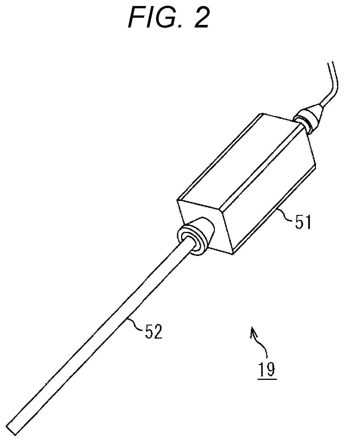
[0078]FIG. 5 is a block diagram illustrating exemplary configurations of the CCU 12 and the endoscope 19.

[0079]As illustrated in the left half of FIG. 5, the camera head 51 includes an imaging element 111, an imaging element driver 112, a lens driver 113, a zoom lens driving unit 114, and a focus lens driving unit 115.

[0080]The imaging element 111 includes, for example, a CMOS image sensor or a CCD image sensor. The imaging element 111 converts an optical image focused on an imaging surface into an electric signal by photoelectric conversion and outputs the electric signal as a photographic signal to the CCU 12.

[0081]The imaging element driver 112 is a driver for driving the imaging element 111. The imaging element driver 112 allows the imaging element 111 to perform a predetermined operation such as a photographing operation or a reset operation by outputting a drive signal. For example, a shutter speed of the imaging element 111 is co...

second embodiment

ing Mask Region on the Basis of AF Evaluation Value

[0118]The mask region may be detected on the basis of the AF evaluation value obtained by the AF sampling unit 135 instead of the sampling value obtained by the sampling unit 133.

[0119]First Exemplary Setting

[0120]FIG. 9 is a diagram illustrating an exemplary setting of the sampling frames in a case where the mask region is detected on the basis of the AF evaluation value.

[0121]As indicated by the sampling frames F1 to F4 of the left photographic image of FIG. 9, the sampling frame gate 132 sets sampling frames, for example, having a narrow strip shape in the upper, lower, left, and right ends of the photographic image. The sampling frames F1 to F4 are set, for example, under control of the lens controller 136.

[0122]The sampling frames F1 and F2 indicated by one-dotted chain lines are sampling frames for detecting upper and lower edges, respectively, of the mask region. In addition, the sampling frames F3 and F4 indicated by dotted ...

third embodiment

Setting of Evaluation Value Calculation Target Region

[0147]FIGS. 12A and 12B are diagrams illustrating an exemplary setting of the evaluation value calculation target region.

[0148]As illustrated in FIGS. 12A and 12B, the lens controller 136 sets the evaluation value calculation target region serving as a target region for calculating the AF evaluation value inside the effective region so as not to overlap with the mask region. For example, the evaluation value calculation target region is set by magnifying or reducing a size of a default area and shifting a default center position on the basis of the detection result of the mask region.

[0149]The oblong area A1 of FIG. 12A is an evaluation value calculation target region set inside the effective region having a diameter shorter than the vertical length of the photographic image. The area A2 of FIG. 12B is an evaluation value calculation target region set inside the effective region having a diameter longer than the vertical length of...


PUM


Abstract

A system includes an endoscope including a scope and an image sensor. The image sensor is configured to capture medical image data that includes effective image portion data and a mechanical vignetting portion data, the mechanical vignetting portion data of the medical image data being generated due to mechanical vignetting caused by a difference in the image sensor which generates the medical image data and the scope. There is also circuitry configured to determine evaluation information from image data which is from the effective image portion data, and execute a control process to at least partially control at least one of an autofocus processing, and an auto white balance processing on the endoscope on the basis of the evaluation information.

Description

TECHNICAL FIELD[0001]The present technology relates to an endoscope system, a control method, an information processing device, and a program, and more particularly, to an endoscope system, a control method, an information processing device, and a program capable of photographing an endoscopic image suitable for a surgical operation.CROSS REFERENCE TO RELATED APPLICATIONS[0002]This application claims the benefit of Japanese Priority Patent Application JP 2018-051955 filed on Mar. 20, 2018, the entire contents of which are incorporated herein by reference.BACKGROUND ART[0003]In recent years, an endoscopic surgical operation having low invasiveness has attracted attention. In order to obtain an endoscopic image suitable for the surgical operation, an endoscope having an autofocus (AF) function, an automatic exposure (AE) function, and an auto white balance (AWB) function has been proposed.[0004]For example, PTL 1 discloses a technique of performing the AF function of the endoscope by ...

Claims


Application Information

Patent Timeline
IPC IPC(8): G06T7/00A61B1/00A61B1/05A61B1/06H04N5/232H04N9/73G06T7/80
CPCG06T7/0012A61B1/00188A61B1/05A61B1/0661H04N2005/2255H04N5/232123H04N9/735G06T7/80A61B1/00096A61B1/045G06T7/0002G06T2207/30168A61B1/000095H04N23/555H04N23/673H04N23/60G06T2207/10068H04N23/88
Inventor KAWAI, TAKASHIHOSONO, KIYOSHI
Owner SONY CORP
Why Eureka
Try Eureka