Power conversion device

Active Publication Date: 2021-01-28
MITSUBISHI ELECTRIC CORP
View PDF0 Cites 4 Cited by
  • Summary
  • Abstract
  • Description
  • Claims
  • Application Information

AI Technical Summary

Benefits of technology

[0011]According to the present invention, when the AC effective voltage in the AC distribution system deviates from the voltage range defined by the dead zone information, the AC effective voltage in the AC distribution system can be returned to fall within the voltage range by autonomous control of the active power and the reactive power by the power conversion device. As

Problems solved by technology

As described above, when renewable energy of a solar cell and the like is supplied in large quantity, there occurs a problem in the case of a solar cell that the voltage in a distribution system rises in a time zone of daytime with a large

Method used


Image

  • Power conversion device
  • Power conversion device
  • Power conversion device

Examples


first embodiment

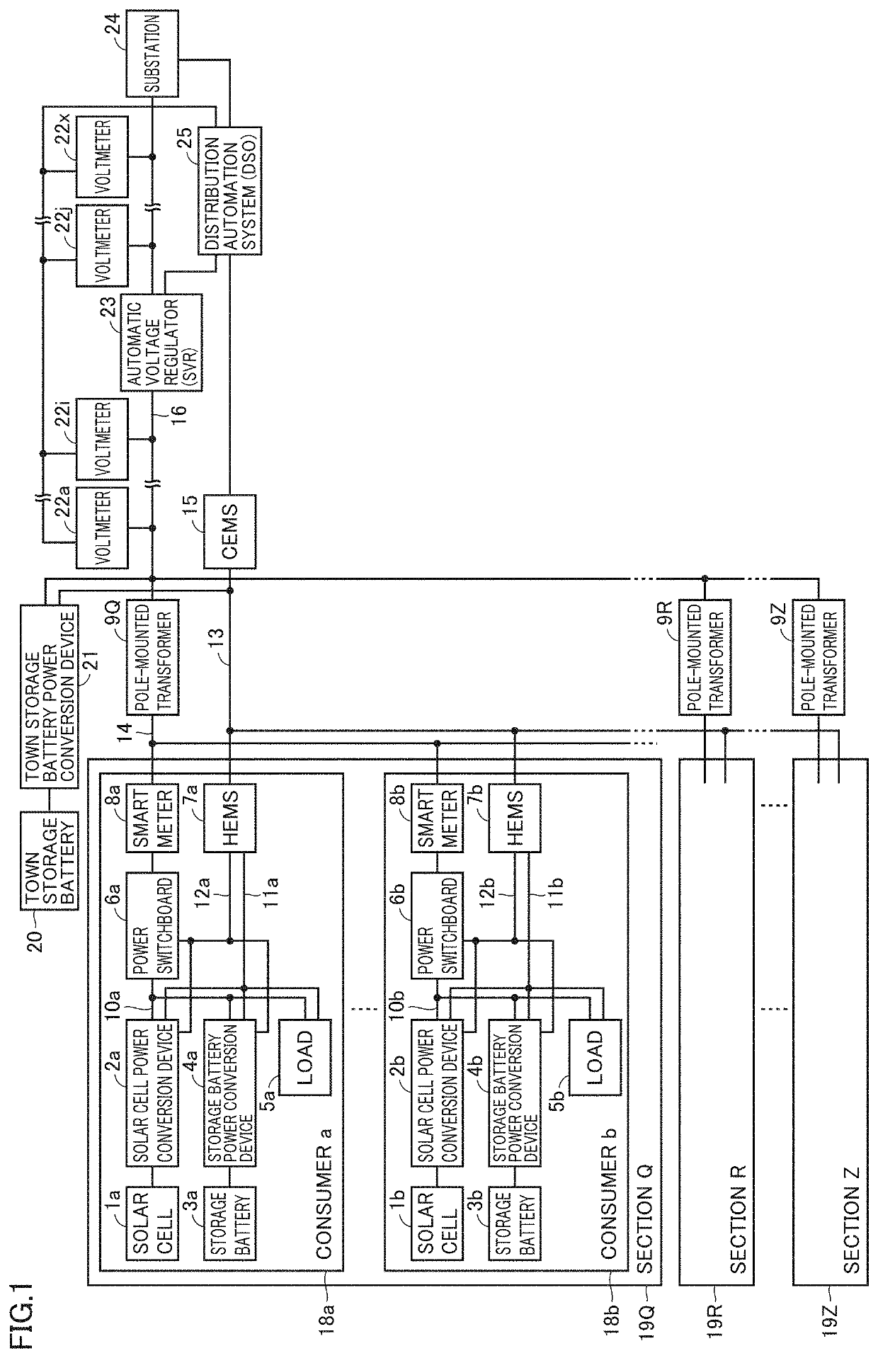
[0045]FIG. 1 is a block diagram showing a configuration of a distributed power supply system to which a power conversion device according to the first embodiment of the present invention is applied.

[0046]Referring to FIG. 1, the distributed power supply system is disposed in a smart town formed of a collection of a plurality of sections (for example, about 30 sections). Each of the sections forming such a smart town is constituted of a plurality of (for example, about ten) consumers connected to a common pole-mounted transformer. FIG. 1 shows sections 19Q, 19R and 19Z, and pole-mounted transformers 9Q, 9R and 9Z that correspond to sections 19Q, 19R and 19Z, respectively, but any number of sections may be provided. Furthermore, a consumer a and a consumer b are shown in section 19Q, but any number of consumers may exist.

[0047]Each consumer house 18 includes a solar cell 1, a solar cell power conversion device 2, a storage battery 3, a storage battery power conversion device 4, a load...

second embodiment

[0265]The first embodiment has been described with regard to an example in which the dead zone information width notified to solar cell power conversion device 2 is processed by HEMS 7 into two types and the dead zone width information notified to storage battery power conversion device 4 is also processed by HEMS 7, with the result that a total of three different types of dead zone width information is notified from the HEMS to the power conversion device.

[0266]In the second embodiment, the dead zone width information is not processed as in the first embodiment. Also, the target voltage of the system voltage (consumer premises distribution system 10) at the time of system voltage stabilization control and the end determination voltage for the system voltage stabilization control by reactive power output are differently calculated. In addition, as to the control configuration, the second embodiment is different from the first embodiment in the configurations of voltage control targe...

third embodiment

[0289]The third embodiment will be described with regard to the case where, in contrast to the first embodiment, HEMS 7 generates one type of dead zone information width to be notified to solar cell power conversion device 2 and also generates two types of dead zone width information to be notified to storage battery power conversion device 4, thereby obtaining a total of three different types of dead zone width information, which is then notified to each power conversion device.

[0290]FIG. 31 is a conceptual diagram illustrating the dead zone width information, the target voltage at the time of system voltage stabilization control, and the end determination voltage for system voltage stabilization control by reactive power output in the third embodiment.

[0291]Referring to FIG. 31, in the third embodiment, HEMS 7 sets two types of dead zone widths of storage battery power conversion device 4 in accordance with the comparison between the electric power generated by solar cell 1 and th...


PUM


Abstract

A solar cell power conversion device is disposed between a solar cell and a consumer premises distribution system. A storage battery power conversion device is disposed between a storage battery and the consumer premises distribution system. When an AC effective voltage in the consumer premises distribution system deviates from a voltage range defined in accordance with dead zone information transmitted from HEMS, system voltage stabilization control for returning the AC effective voltage to fall within the voltage range is performed by control of active power and reactive power that are output from a first DC/AC conversion circuit and a second DC/AC conversion circuit.

Description

TECHNICAL FIELD[0001]The present invention relates to a power conversion device, and more particularly to output control of a distributed power supply by a power conversion device that performs, with an alternating current, system interconnection of distributed power supplies such as an energy creating device harnessing renewable energy, such as a solar cell (hereinafter also referred to as an “energy creation device”), and an energy storing device such as a storage battery (hereinafter also referred to as an “energy storage device”).BACKGROUND ART[0002]In recent years, for reducing environmental burdens, a power generation system that harnesses natural energy, such as a solar cell not emitting carbon dioxide, has come into widespread use in houses. Furthermore, in order to address power shortage and the like since the Great East Japan Earthquake, product commercialization has been underway for a system including a storage battery, a system utilizing an electric vehicle as a storage...

Claims


Application Information

Patent Timeline
IPC IPC(8): H02J3/16H03M1/00H02S40/32H02S40/38
CPCH02J3/16H02S40/38H02S40/32H03M1/001H02M7/48Y02B10/10Y02E10/56Y02E40/30H02J3/32H02J3/381H02J2300/26Y02E70/30
Inventor INOUE, SADAYUKITAKANO, TOMIHIRO
Owner MITSUBISHI ELECTRIC CORP
Why Eureka
Try Eureka