
Method of generation of planar plasma jets

Active Publication Date: 2021-01-28
DREXEL UNIV +1
View PDF0 Cites 1 Cited by
  • Summary
  • Abstract
  • Description
  • Claims
  • Application Information

AI Technical Summary

Benefits of technology

The present invention relates to a plasma generator for forming a plasma jet, which includes a dielectric body with a cavity and a high voltage electrode and a grounded electrode. The width of the cavity is greater than the height and the aperture has a width of less than the width of the high voltage electrode. The plasma generator has a distance between the high voltage electrode and the grounded electrode of greater than 10% to prevent electrical connection. The gas inlet has a volume and velocity sufficient to prevent air from entering the cavity. The aperture has a width of at least 1 cm and a ratio of width to height of at least 3:1. The plasma generator can be used for cancer therapy, including plasma-induced immunotherapy, with parameters such as treatment time, excitation voltage, pulse repetition frequency, and pulse width.

Problems solved by technology

One of the important challenges and limitations of existing one dimensional (1D) plasma jets is their relatively low area of treatment [13-19] which results from the small size of the plasma jet.
These methods often do not rely on the patient's adaptive immune responses for the resolution of cancer.
Thus, once cells escape treatment, they continue to grow, resulting in tumor recurrence and resistance to therapy.

Method used


Image

  • Method of generation of planar plasma jets
  • Method of generation of planar plasma jets
  • Method of generation of planar plasma jets

Examples


examples

[0087]The following examples are illustrative, but not limiting of the methods and compositions of the present disclosure.

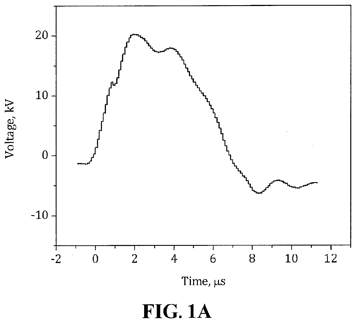
[0088]A microsecond-pulsed high voltage power supply with an output of 20 kV peak-to-peak, a pulse duration of ˜8 μs (FIG. 1A), and a frequency of 500 Hz [31] was employed. Plasma jets were generated in He flow (99%, Airgas). To monitor the discharge development and propagation of ionization waves a 4 Picos ICCD camera from Stanford Computer Optics triggered using a P6015A high-voltage probe (75-MHz bandwidth, Tektronix) was connected to a 1-GHz DPO-4104B oscilloscope (Tektronix).

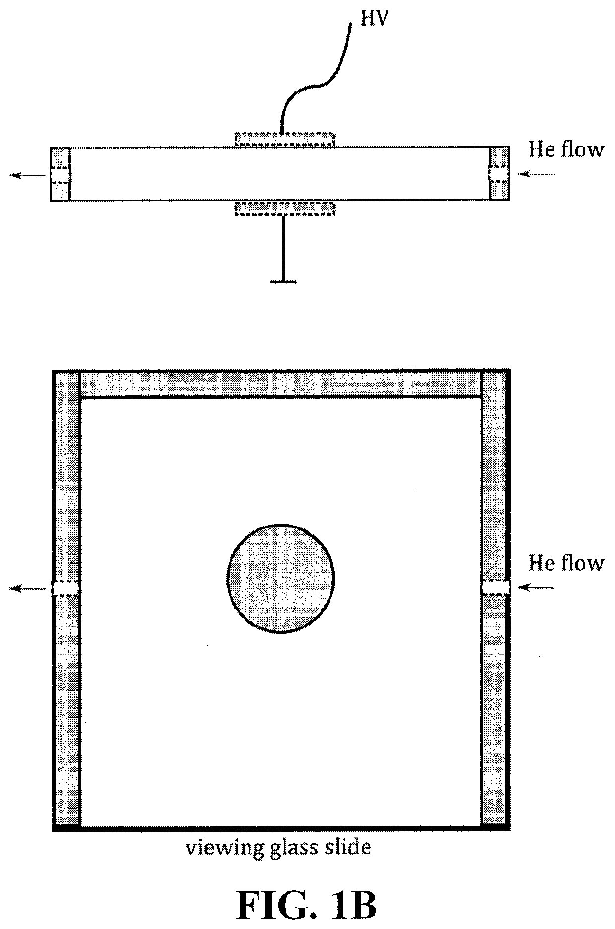
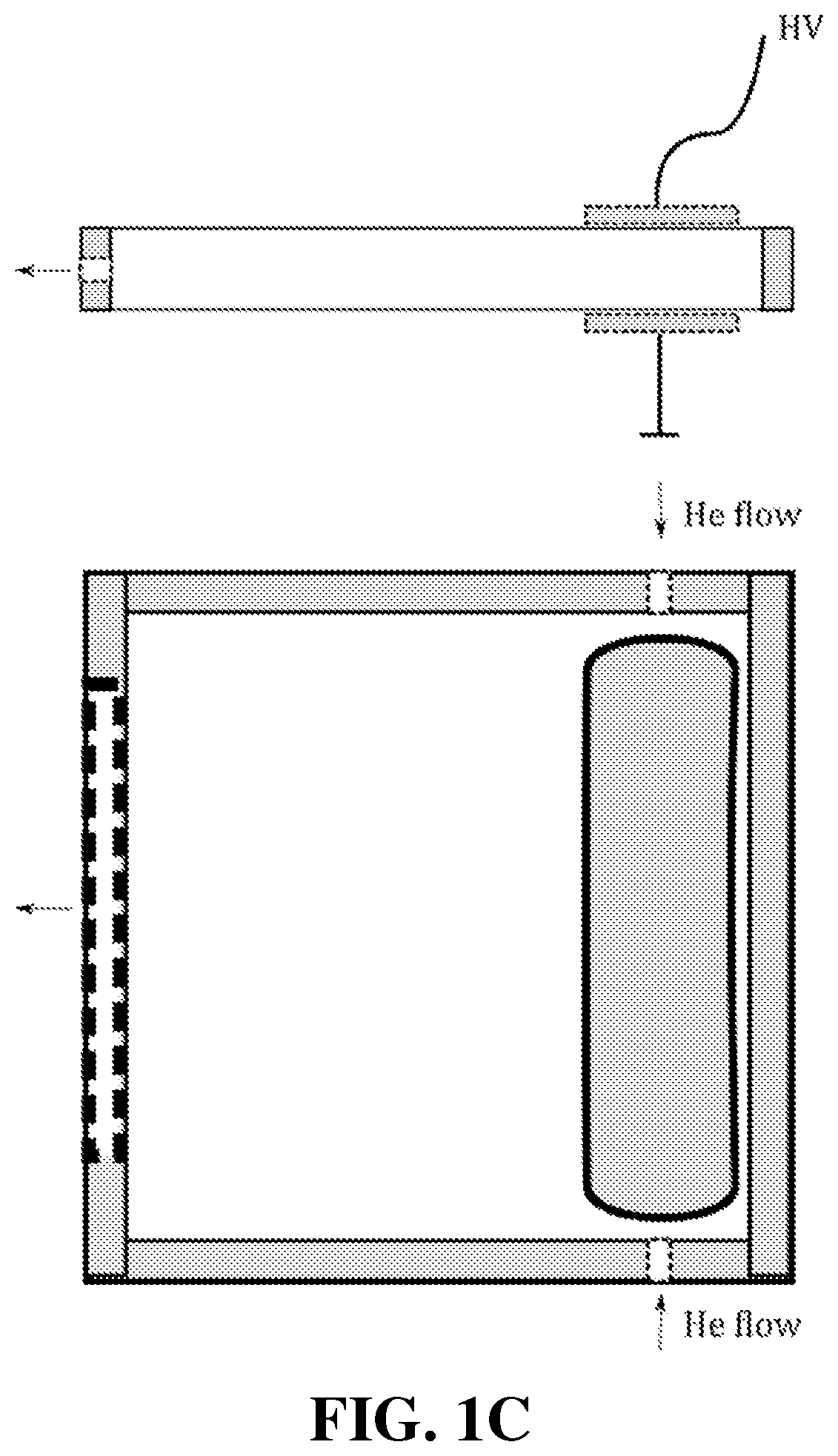
[0089]Two different discharge chambers were used for generation and imaging of DBD, surface ionization waves, plasma “bullets” and a rectangular plasma jet. Both chambers were made of two 1 mm thick 75×75 mm glass slides separated by a 5 mm thick dielectric to form a rectangular cuboid with a cavity therein. The first setup, used to study DBD development and propagation of surface ioniza...


PUM


Abstract

Applications of dielectric barrier discharge (DBD) based atmospheric pressure plasma jets are often limited by the relatively small area of treatment due to their 1D configuration. This system generates 2D plasma jets permitting fast treatment of larger targets. DBD evolution starts with formation of transient anode glow, and continues with development of cathode-directed streamers. The anode glow can propagate as an ionization wave along the dielectric surface through and outside of the discharge gap. Plasma propagation is not limited to 1D geometry such as tubes, and can be organized in a form of a rectangular plasma jet, or other 2D or 3D shapes. Also described are a method for generating 2D plasma jets and use of the 2D plasma jets for cancer therapy.

Description

CROSS REFERENCE TO RELATED APPLICATIONS[0001]This application claims the benefit of U.S. Provisional Application No. 62 / 632,788, filed on Feb. 20, 2018, the entire disclosure of which is hereby incorporated by reference as if set forth fully herein.STATEMENT OF GOVERNMENT INTEREST[0002]This invention was made with government support under Contract No. DE-SC0016492 awarded by the Department of Energy. The Government has certain rights in the invention.FIELD OF THE INVENTION[0003]The present invention relates to a plasma generator for forming a plasma jet with improved treatment of large surface area targets.BACKGROUND OF THE INVENTION[0004]Non-thermal atmospheric plasma jets (APPJ) based on dielectric barrier discharge (DBD) have attracted considerable interest in the recent decades [1-3]. Multiple research groups have studied these plasma sources for various applications like surface modification [5, 6], decontamination [6-9], cancer treatment [10-12], including plasma-induced immun...

Claims


Application Information

Patent Timeline
IPC IPC(8): H05H1/24
CPCH05H1/2406H05H2240/20H05H2001/2443H05H2245/122H05H2240/10H05H1/2443H05H1/2439H05H2245/32
Inventor DOBRYNIN, DANIL V.FRIDMAN, ALEXANDERLIN, ABRAHAMMILLER, VANDANASNOOK, ADAM
Owner DREXEL UNIV
Learn More