Deposition of organic films

a thin film, organic technology, applied in the direction of liquid surface applicators, chemical vapor deposition coatings, coatings, etc., can solve the problems of difficult control of thin film formation on a substrate, difficult to fill gaps of very small features, and limited spin-applied film tailoring,

Active Publication Date: 2017-12-07
ASM IP HLDG BV
View PDF5 Cites 60 Cited by
  • Summary
  • Abstract
  • Description
  • Claims
  • Application Information

AI Technical Summary

Benefits of technology

[0008]In some aspect, processes for selectively depositing an organic film on a substrate comprising a first surface and a second surface are provided. In some embodiments the process may comprise one or more deposition cycles comprising contacting the substrate with a first vapor phase precursor, and contacting the substrate with a second vapor phase precursor, wherein contacting the substrate with the first and second vapor phase precursors forms the organic thin film selectively on the first surface relative to the second surface. In some embodiments processes may further comprise repeating the contacting steps until an organic thin film of a desired thickness has been formed. In some embodiments the first surface may be a metallic surface. In some embodiments the second surface may be a dielectric surface. In some embodiments the organic film may comprise a polyimide film. In some embodiments the substrate may be contacted with the second vapor phase precursor before the substrate is contacted with the first vapor phase precursor. In some embodiments the first vapor phase precursor may comprise a diamine. In some embodiments the substrate is contacted with the first vapor phase precursor comprising a diamine before it is contacted with another, different precursor.

Problems solved by technology

However, tailoring of spin-applied films is limited for several reasons.
For instance, formation of uniform thin films on a substrate is difficult to control, in part because of the viscosity of the starting liquid, and it can be difficult to fill the gaps of very small features (e.g., trenches or gaps between metal lines) without void generation after curing.
Also, spin-coating over high topography relative to the desired thickness of the layer can result in discontinuous and non-conformal deposition.

Method used


Image

  • Deposition of organic films
  • Deposition of organic films
  • Deposition of organic films

Examples


example 1

[0113]Sample polyimide thin films were deposited on a number of substrates according to selective deposition processes described herein. 200 mm silicon wafers having tungsten (W) features alternated with silicon oxide surfaces were used as substrates. The width of the tungsten features was 250 nm with a pitch of approximately 600 nm. The polyimide deposition processes were performed in a Pulsar 3000® cross-flow ALD reactor connected with PRI cluster tool.

[0114]A first batch of sample polyimide films were deposited according to the processes described herein using DAH as a first vapor phase reactant and PMDA as a second vapor phase reactant. The DAH first reactant was supplied at 45° C. by an N2 carrier gas having a flow rate of 450 sccm. The DAH pulse time was 5 seconds and the DAH pure time was 4 seconds. The PMDA second reactant was supplied to the reaction chamber at 180° C. by an N2 carrier gas having a flow rate of 450 sccm. The PMDA pulse time was 11 seconds and the PMDA purge...

example 2

[0118]A first sample polyamide film was deposited on a 200 mm silicon wafer having patterned tungsten (W) features alternated with silicon oxide surfaces. A second sample polyamide film was deposited on a crystalline silicon wafer having 1.5 nm of native oxide. The samples were deposited according to the processes described herein using adipoyl chloride (AC) as a first vapor phase reactant and ethylene diamine (EDA) as a second vapor phase reactant. The AC first reactant was vaporized at a temperature of 50° C. and supplied to the reaction chamber at a temperature of 65° C. with a line flow of 500 sccm. The AC pulse and purge times were 2.5 seconds. A pulsing pressure of about 180 Torr was used and the conduit through which the AC was supplied was fitted with a line filter. The ED second reactant was supplied at room temperature with pulse and purge times of ⅕ seconds. A pulsing pressure of about 100 Torr was used and the conduit through which the ED was supplied was not fitted with...

example 3

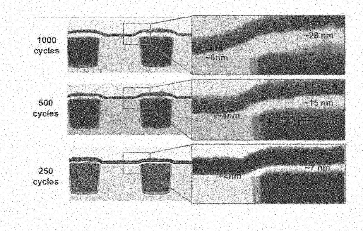
[0121]A sample polyimide film was selectively deposited on a 200 mm silicon wafer having patterned tungsten (W) features alternated with silicon oxide surfaces according to the processes described herein using DAH as a first vapor phase reactant and PIVIDA as a second vapor phase reactant. The DAH first reactant was supplied at 45° C. by an N2 carrier gas having a flow rate of 450 sccm. The DAH pulse time was 5 seconds and the DAH pure time was 4 seconds. The PIVIDA second reactant was supplied to the reaction chamber at 180° C. by an N2 carrier gas having a flow rate of 450 sccm. The PMDA pulse time was 11 seconds and the PMDA purge time was 4 seconds. The reaction temperature was 190° C. The polyimide sample film was deposited using 1000 deposition cycles. The polyimide was deposited on the W surface, with a film thickness of about 30 nm. A substantially lesser amount of polyimide was deposited on the silicon oxide surface, about 4 nm, as shown in FIG. 6A.

[0122]The sample polyimid...


PUM

PropertyMeasurementUnit
temperatureaaaaaaaaaa
diametersaaaaaaaaaa

Abstract

Processes are provided herein for deposition of organic films. Organic films can be deposited, including selective deposition on one surface of a substrate relative to a second surface of the substrate. For example, polymer films may be selectively deposited on a first metallic surface relative to a second dielectric surface. Selectivity, as measured by relative thicknesses on the different layers, of above about 50% or even about 90% is achieved. The selectively deposited organic film may be subjected to an etch process to render the process completely selective. Processes are also provided for particular organic film materials, independent of selectivity.

Description

CROSS-REFERENCE TO RELATED APPLICATIONS[0001]The present application is related to U.S. application Ser. No. 15 / 070,594, filed Mar. 15, 2016, entitled “VAPOR PHASE DEPOSITION OF ORGANIC FILMS,” and to U.S. application Ser. No. 14 / 879,962, filed Oct. 9, 2015, entitled “VAPOR PHASE DEPOSITION OF ORGANIC FILMS” the disclosures of which are hereby incorporated by reference in their entireties.BACKGROUNDField[0002]The present disclosure relates to deposition of organic thin films, including selective deposition on a first surface of a substrate relative to a second surface. Processes are also provided for particular organic film materials, independent of selectivity.Description of the Related Art[0003]Organic thin films have valuable optical, thermal, electrical and mechanical properties and are widely used in the electronics, medical engineering, defense, pharmaceutical, and micro- and nanotechnology industries. Polymers in the microelectronics and photonics industries include, among ot...

Claims


Application Information

Patent Timeline
Patent Type & Authority Applications(United States)
IPC IPC(8): H01L21/02H01L21/3065H01L21/285H01L21/311C23C16/56C23C16/455C23C16/04H01L21/768B05D1/00
CPCH01L21/3065H01L21/76826H01L21/28562H01L21/02118B05D1/60H01L21/31138C23C16/56C23C16/45553H01L21/0228H01L21/76834C23C16/04
Inventor TOIS, EVA E.SUEMORI, HIDEMIPORE, VILJAMI J.HAUKKA, SUVI P.SHARMA, VARUN
Owner ASM IP HLDG BV
Why Eureka
Try Eureka