Charging systems for charging electrical energy storage devices of electric vehicles and associated methods

a charging system and electric vehicle technology, applied in charging stations, propulsion parts, transportation and packaging, etc., can solve the problems of limited achievable dynamic range of measuring converters and measuring meters, inability to measure electrical energy or power in a manner, etc., and achieve high resistance

Active Publication Date: 2021-02-18
SIEMENS AG
View PDF0 Cites 3 Cited by
  • Summary
  • Abstract
  • Description
  • Claims
  • Application Information

AI Technical Summary

Benefits of technology

[0019]The charging system may include a first switching device between the at least one converter element and the charging output, a second switching device between the input and the charging output, and a control device for controlling the first switching device and the second switching device. The electrical connection between the at least one converter element and the charging output may be switched with the aid of the first switching device. The electrical connection between the input of the charging system and the charging output may be switched by the second switching device. The first switching device and the second switching device may be driven with the aid of the control device. It is thus possible to switch over from the direct current charging to the alternating current charging in a simple manner.
[0020]In a further embodiment, the charging system is configured to output a predetermined signal upon switching over from the direct current charging to the alternating current charging. If the charging system decides to change to the AC charging, the charging system may signal this to the electric vehicle by way of the protocol in accordance with ISO 15118 and may start a new charging process based on IEC 61851 alone. For this purpose, by way of example, the state “State E” may be signaled for a short time. In order to avoid manipulations, the State E signaling may be performed in such a way that instead of the normatively required voltage of 0 V, a higher voltage is applied across a resistor having a high resistance. Actual unplugging of a charging cable may be identified in this way. In parallel with this, the entire fast charging section will be released and may optionally be used in a different way.

Problems solved by technology

Presently available measuring devices for high direct currents achieve a dynamic range of the current between 20 Amps (A) and 550 A. With such measuring devices, it is therefore not possible to measure the electrical energy or power in a manner that conforms to calibration laws and standards in the case of trickle charging on account of the required accuracy and the limited achievable dynamic range of the measuring converters and measuring meters.

Method used


Image

  • Charging systems for charging electrical energy storage devices of electric vehicles and associated methods
  • Charging systems for charging electrical energy storage devices of electric vehicles and associated methods
  • Charging systems for charging electrical energy storage devices of electric vehicles and associated methods

Examples


Embodiment Construction

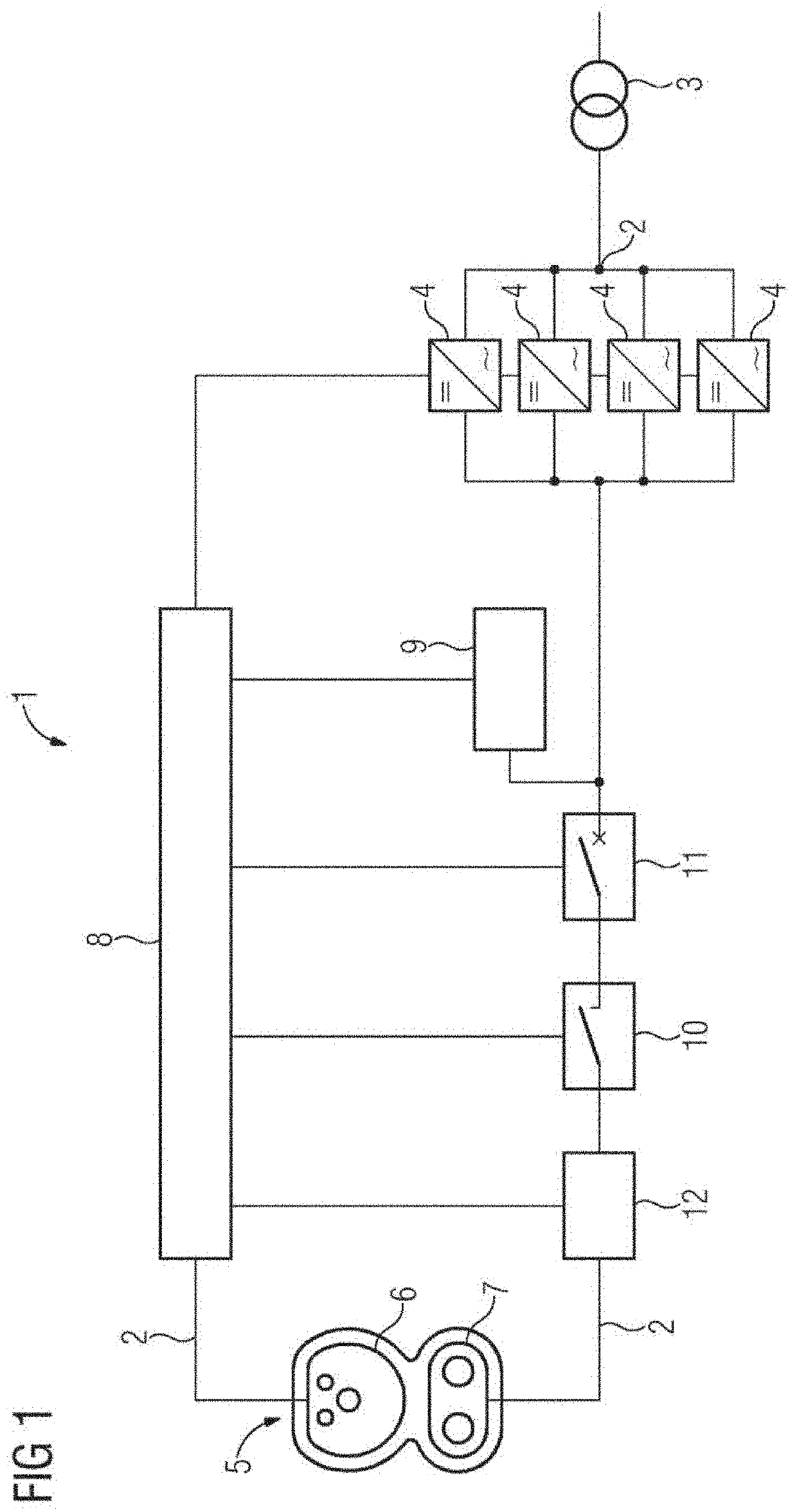
[0036]FIG. 1 depicts a charging system 1 in accordance with the prior art in a schematic illustration. The charging system 1 includes an input 2, which is connected to an electrical energy source 3. The electrical energy source 3, which may be provided by a power supply system, for example, serves to provide an alternating current and / or an AC voltage. Furthermore, the charging system 1 includes at least one converter element 4. In the present exemplary embodiment, the charging system 1 includes four converter elements 4, which are electrically connected in parallel. The converter elements 4 are rectifiers. The alternating current present at the input 2 may be converted into a direct current by the rectifiers or the converter elements 4.

[0037]Furthermore, the charging system 1 includes a charging output 5, to which an electric vehicle may be connected in order to charge the electrical energy storage device of the electric vehicle. The charging output 5 includes an AC part 6, which m...


PUM


Abstract

The disclosure relates to a charging system for charging an electrical energy storage device in an electric vehicle. The charging system includes: an input for an alternating current, which is provided with a source of electrical energy, at least one transformer element for transforming the alternating current into a direct current, and a charge output for connecting the charging system to the electric vehicle. The charging system is configured to connect the at least one transformer element to the charge output for charging the electrical energy storage device with direct current. The charging system is further configured to connect the input to the charge output for charging the electrical energy storage device with alternating current.

Description

[0001]The present patent document is a § 371 nationalization of PCT Application Serial No. PCT / EP2019 / 053832, filed Feb. 15, 2019, designating the United States, which is hereby incorporated by reference, and this patent document also claims the benefit of German Patent Application No. 10 2018 204 126.1, filed Mar. 19, 2018, which is also hereby incorporated by reference.TECHNICAL FIELD[0002]The present disclosure relates to charging systems for charging electrical energy storage devices of electric vehicles. Furthermore, the present disclosure relates to methods for charging electrical energy storage devices of electric vehicles.BACKGROUND[0003]At the present time, interest is being directed at charging systems for charging electrical energy storage devices of electric vehicles. Such an electric vehicle may be a purely electrically driven vehicle or a hybrid vehicle. Various charging systems and charging methods are known from the prior art. By way of example, so-called direct curr...

Claims


Application Information

Patent Timeline
Patent Type & Authority Applications(United States)
IPC IPC(8): B60L53/10H02J7/00H02J7/04B60L53/16B60L53/66B60L53/62
CPCB60L53/11H02J7/00045H02J7/0047H02J7/04B60K6/28B60L53/66B60L53/62H02J2207/20B60L2210/30B60L53/16B60L53/14B60Y2200/91B60Y2200/92B60Y2300/91
Inventor BODE, SEBASTIAN
Owner SIEMENS AG
Why Eureka
Try Eureka