Electromagnetic radiation of nanometer range generating device

Pending Publication Date: 2021-02-25
NASER TECH OU
View PDF7 Cites 0 Cited by
  • Summary
  • Abstract
  • Description
  • Claims
  • Application Information

AI Technical Summary

Benefits of technology

[0015]On the basis of the phenomenon described above, a device was created for generation of nanometre range electromagnetic radiation, which makes it possible to achieve the above technical result. It includes at least two devices for adjusting electrical power, at least one phase shifting device, at least one electromagnetic wave emitter, at least two exciting and one excited inductors. The excited inductor is connected to the emitter of electromagnetic waves, while both exciting inductors with the same electrical parameters are connected to the AC network through electric power adjustment devices, enabling electric signals with equal amplitudes. The first exciting inductor is connected to the adjusting device through a phase shifting device, which makes it possible to adjust the phase angle between the signals on the first and second exciting inductors and therefore provide creation of the uniformly variable counter-fluxes of mutual induction by the alternating currents of the exciting inductors. The interaction of these uniformly variable magnetic fluxes with the excited inductor makes the movement of conduction electrons in its winding spiral and alternate, providing generation of electromagnetic radiation in the nanometre range.
[0016]To sum up, the claimed device allows to create conditions under which the movement of free electrons in a metal acquires a variable spiral character, the kinetic energy of the electrons' movement quantizes and electronic transitions from higher energy levels to lower levels are accompanied by the emission of an electromagnetic wave.

Problems solved by technology

The stated disadvantages of the known devices show that there is a task consisting in the creation of such a solution that would ensure the efficient generation of electromagnetic radiation of the nanometre range with low power consumption and with a simple technical design.
The technical problem of obtaining such radiation is caused by the need to create conditions under which the motion of free electrons in a metal acquires a variable spiral character, the kinetic energy of the electrons' motion becomes quantized, and the electronic transitions from higher energy levels to lower ones result the emission of an electromagnetic wave.

Method used


Image

  • Electromagnetic radiation of nanometer range generating device
  • Electromagnetic radiation of nanometer range generating device
  • Electromagnetic radiation of nanometer range generating device

Examples


Embodiment Construction

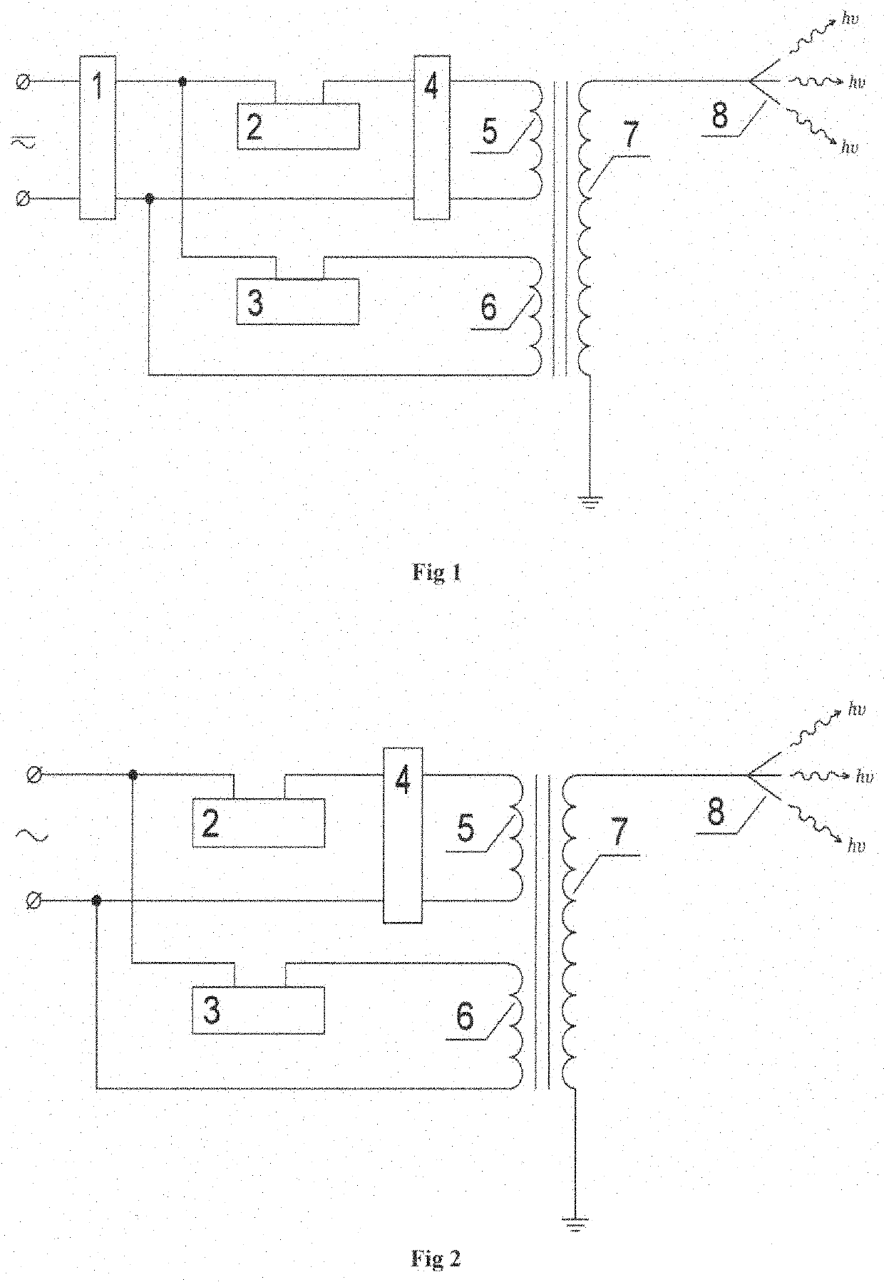
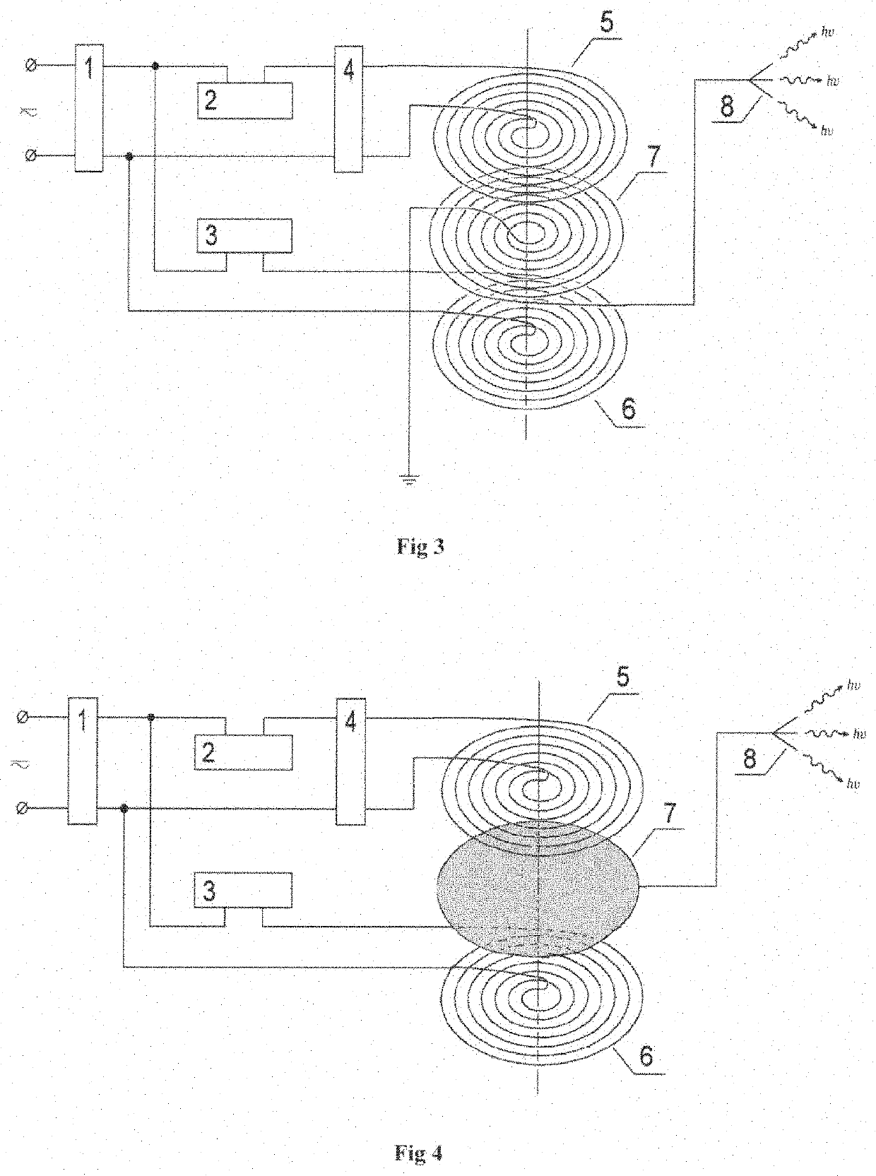
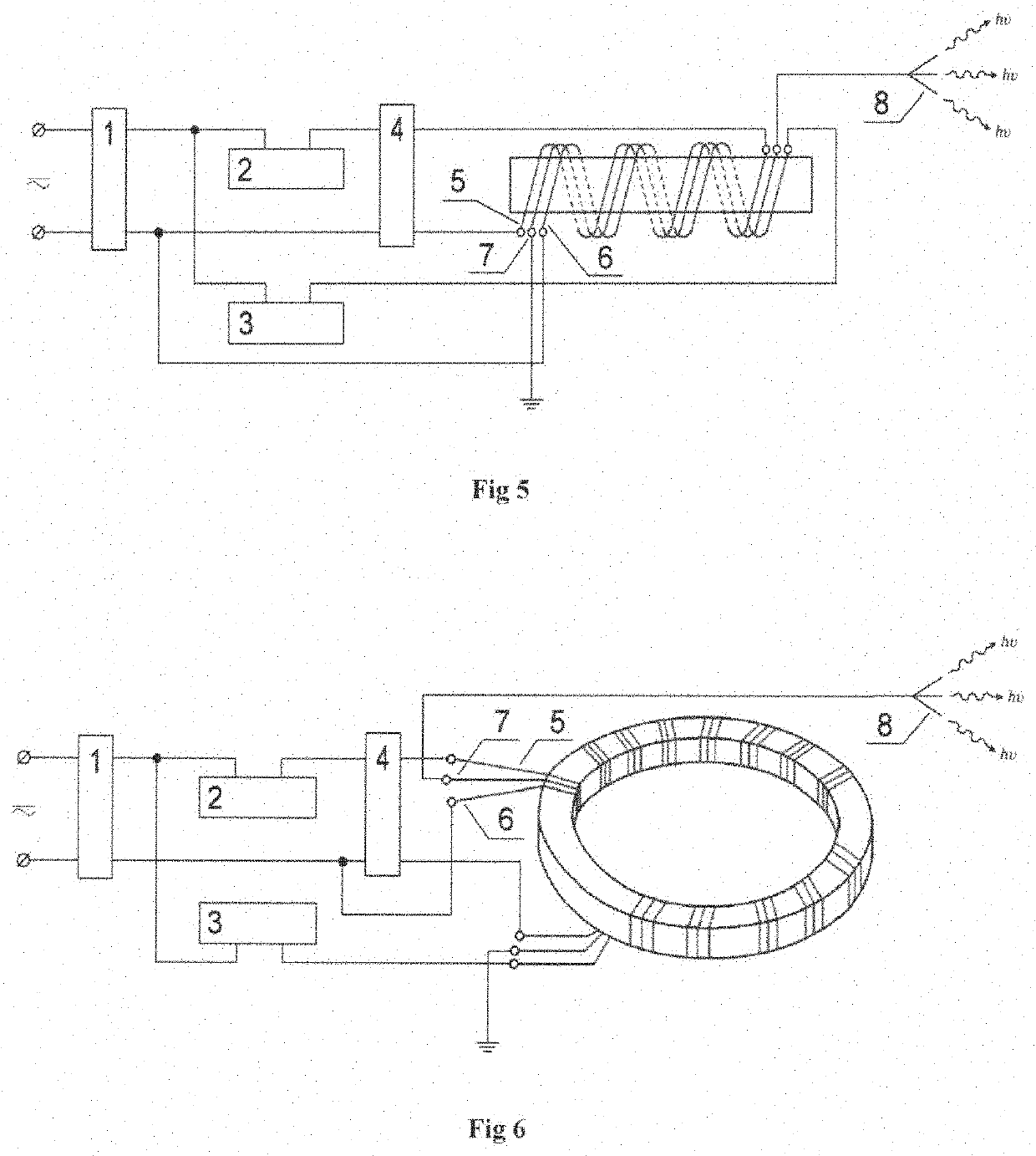
[0057]Electromagnetic radiation of nanometre range generating device comprises the generator of electrical signals of adjustable frequency and amplitude (1), at least two electric power adjustment devices (2) and (3), at least one phase shifting device (4), at least two exciting inductors (5) and (6), the excited inductor (7) and at least one electromagnetic wave emitter (8) (FIG. 1).

[0058]The generator of electrical signals of adjustable frequency and amplitude (1) is connected to the power supply source; the first exciting inductor (5) is connected to the electrical signal generator (1) through the phase shifting device (4) and the first power adjustment device (2), and the second exciting inductor (6)—through the second power adjustment device (3). The first exciting inductor (5) is made coaxial with the second one (6), and the excited inductor (7) is located inside the space between the first (5) and second (6) exciting inductors and coaxially with them. The number of turns in t...


PUM


Abstract

The invention relates to the field of quantum radio physics and is the solid-state quantum generator of nanometer range electromagnetic radiation. It may be widely used in engineering, nanotechnology, physics, biology, chemistry and medicine. The claimed device comprises at least two electric power adjustment devices, at least one phase shifting device, at least one electromagnetic wave emitter, at least two exciting inductors and an excited inductor. It is configured to adjust electrical power in the first and second exciting inductors, allowing to receive electrical signals with equal amplitudes in them.

Description

FIELD OF THE INVENTION[0001]The present invention relates to the field of quantum radio physics and is a solid-state nanometre range electromagnetic radiation quantum generator. It may be widely used in technics, nanotechnology, physics, chemistry, biology and medicine. More specifically, the present invention is applicable to sterilization and gas purification systems, fluorescent lighting devices and so on.BACKGROUND OF THE INVENTION[0002]There are several known types of quantum generators that vary in type of working agent used: solid-state (crystal or glass), gas, semiconductor or dye-based ones. Quantum generators may also vary by the active medium forming particles, which could be molecules, atoms, free or conduction electrons.[0003]There is a conduction electrons-based solid-state cyclotron maser (U.S. Pat. No. 4,376,917), which can produce oscillations at frequency between 300 and 30000 GHz in a submillimetre range. However, it has restrictions on the wavelength or frequency...

Claims


Application Information

Patent Timeline
Patent Type & Authority Applications(United States)
IPC IPC(8): H01S1/00H01S3/09
CPCH01S1/005H01S3/0903H01Q1/50H01Q23/00H01Q1/36H01Q1/364H05G2/00H01F17/045H01F17/062H01F27/2871H01F27/42
Inventor PASTUKHOV, ANDREI
Owner NASER TECH OU
Why Eureka
Try Eureka