Cell treatment apparatus and method for treating cells with lasers

Active Publication Date: 2021-03-11
KATAOKA
View PDF2 Cites 2 Cited by
  • Summary
  • Abstract
  • Description
  • Claims
  • Application Information

AI Technical Summary

Benefits of technology

The present invention provides a cell treatment apparatus and method that can prevent variations in the time it takes to treat cells using laser light.

Problems solved by technology

However, this removing operation requires time and labor, for example, to be performed under a microscope, and there is a problem that the quality of cells and the like obtained differs greatly depending on the skill level of the operator (Patent Literature 1).

Method used


Image

  • Cell treatment apparatus and method for treating cells with lasers
  • Cell treatment apparatus and method for treating cells with lasers
  • Cell treatment apparatus and method for treating cells with lasers

Examples


first embodiment

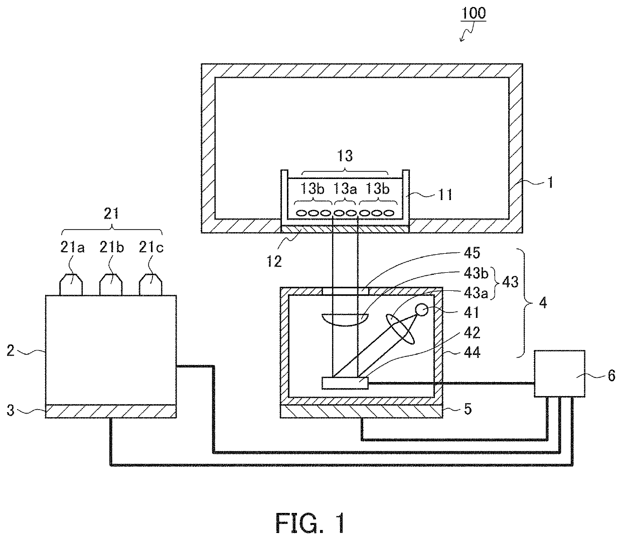
[0030]The present embodiment relates to an example of a cell treatment apparatus. FIG. 1 is a schematic cross-sectional view showing a configuration of a cell treatment apparatus 100 according to the first embodiment. As shown in FIG. 1, the cell treatment apparatus 100 includes a cell treatment chamber 1, an observation unit 2, an observation moving unit 3, a laser projection unit 4, a laser moving unit 5, and a control unit 6 as main components. The cell treatment chamber 1 includes a cell culture vessel placement portion 12 in which the cell culture vessel 11 is placed. The cell culture vessel placement portion 12 is formed as a recess on the bottom surface (the laser projection unit 4 side in FIG. 1) of the cell treatment chamber 1. The bottom surface of the cell culture vessel placement portion 12 is formed of a translucent member that can transmit laser light. The cell culture vessel 11 contains cells 13 and is placed in the cell culture vessel placement portion 12. The cells ...

second embodiment

[0062]The present embodiment relates to an example of a cell treatment apparatus. FIGS. 6 to 15 each show an example of a configuration of the cell treatment apparatus according to the present embodiment. FIG. 6 is a perspective view showing an example of a configuration of the cell treatment apparatus according to the present embodiment, FIG. 7 is a schematic cross-sectional view showing the configurations of the first region, the second region, and the third region in the cell treatment apparatus according to the present embodiment, FIG. 8 is a perspective view showing an example of a configuration of the first region in the cell treatment apparatus according to the present embodiment, FIG. 9 is a cross-sectional view of the first region taken along the line I-I of FIG. 6, FIG. 10A is an exploded perspective view showing an example of a culture vessel placement portion in the cell treatment apparatus according to the present embodiment, FIG. 10B is a cross-sectional view taken alo...

third embodiment

[0112]The present embodiment relates to an example of a treatment method. FIG. 16 is a flow chart showing the process of the treatment method according to the present embodiment. As shown in FIG. 16, the treatment method according to the present embodiment includes the step S4 (acquisition), the step S5 (generation), and the step S6 (treatment). The step S4 and the step S5 are optional, and the treatment method may or may not include these steps.

[0113]In the acquisition step (S4), an image in the cell culture vessel is acquired. In the acquisition step, for example, an image containing cells in the cell culture vessel may be acquired, an image not including cells in the cell culture vessel may be acquired, or both of them may be acquired. In the acquisition step, for example, an image of a part of or the entire cell culture vessel may be acquired. The image may be an image acquired in advance, or may be an image acquired in the acquisition step. In the former case, the image is stor...


PUM


Abstract

The present invention is intended to provide a cell treatment apparatus and a method for treating cells that can suppress a variation of a treatment time of treating cells using laser light. The cell treatment apparatus of the present invention includes: a cell treatment chamber in which cells in a cell culture vessel are treated; an observation unit that can observe the cells; a laser projection unit that can project a laser image onto the cells; a laser moving unit that can move the laser projection unit; and a control unit. The laser projection unit includes: a laser light source; and a laser image generation portion that generates the laser image to be projected onto the cells from laser light oscillated from the laser light source. The control unit controls generation of the laser image by the laser image generation portion. By moving the laser moving unit from a projection start position of the laser image at one end of the cell culture vessel to a projection end position of the laser image at the other end of the cell culture vessel, the laser projection unit projects the laser image from the projection start position of the laser image at one end of the cell culture vessel to the projection end position of the laser image at the other end of the cell culture vessel.

Description

TECHNICAL FIELD[0001]The present invention relates to a cell treatment apparatus and a method for treating cells with lasers.BACKGROUND ART[0002]In recent years, attempts have been made to differentiate target cells, tissues, and the like from pluripotent cells such as induced pluripotent stem cells (iPS cells) and embryonic stem cells (ES cells) and to utilize them for regenerative medicine and drug discovery.[0003]In maintaining the pluripotent cells, some of the proliferating pluripotent cells may differentiate into other cells. In addition, in differentiation from pluripotent cells to target cells or the like, some of differentiated cells may differentiate into cells that are not the target cells.[0004]In such a case, the removal of cells other than the target cells is currently performed manually. However, this removing operation requires time and labor, for example, to be performed under a microscope, and there is a problem that the quality of cells and the like obtained diffe...

Claims


Application Information

Patent Timeline
IPC IPC(8): C12M1/00C12M1/36
CPCC12M39/00C12M41/48C12M31/04C12Q1/02C12M41/36C12M35/02C12M31/02
Inventor MATSUMOTO, JUNICHIHONDA, SHOICHI
Owner KATAOKA
Why Eureka
Try Eureka